
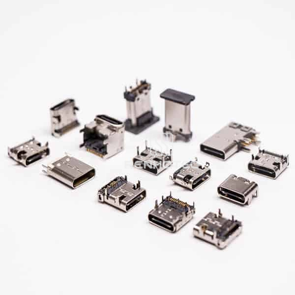
USB combines a physical connection with specifications for communication and power. Choosing a connector requires checking both its mechanical form and the functions supported by the equipment and cable.
Connector form and USB capability
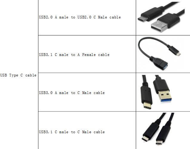
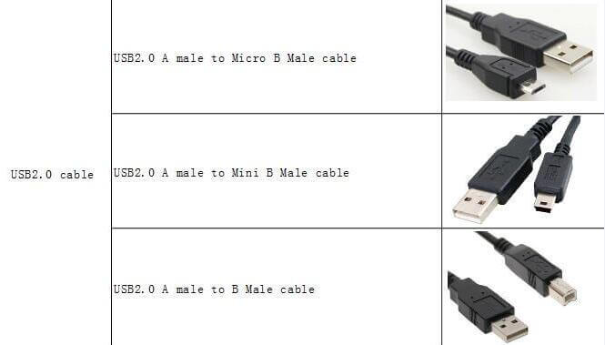
Type-A, Type-B, Mini, Micro and Type-C identify connector forms. The form alone does not establish a supported data rate or power level. For a USB 2.0 or USB 3.0 connection, confirm the connector contacts, cable wiring and the host and device capabilities together.
USB Type-C provides a reversible mating interface. A Type-C port does not automatically provide a particular data speed, USB Power Delivery or video output. DisplayPort or other video connections require the appropriate support in the equipment and, where applicable, the cable or adapter.
Board mounting and mechanical fit
Check the footprint, mounting height, mating direction and shell fixing points against the PCB and enclosure. Surface-mount contacts, through-hole contacts and cable termination options have different assembly requirements. Connector retention and accessible mating space also matter in the finished equipment.
Electrical and environmental requirements
Use the selected part specification for current rating, contact resistance, insulation resistance, dielectric withstand voltage and operating temperature. These are different characteristics and should not be inferred from the USB connector family. Shielding, sealing and mating durability likewise need confirmation for the particular part and its assembly conditions.
Define the cable assembly
Specify both connector ends, cable length, required data capability, power requirements and any shielding or mechanical constraints. A matching connector shape alone does not establish protocol, video or power compatibility.