
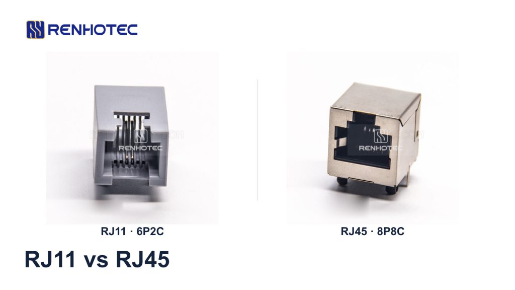
RJ11 usually refers to a six-position modular connection used for telephone or DSL lines. RJ45 commonly refers to the eight-position, eight-contact connection used for Ethernet. The six-position mating interface is narrower, but size alone cannot tell you what signal a port carries.
When identifying an unfamiliar connector, check the available contact positions, the metal contacts actually fitted and the equipment’s port label. Those three observations help you choose a cable or replacement jack without relying on the name printed in a listing.
RJ11 and RJ45: a real connector comparison
These Renhotec PCB sockets show two common configurations. A socket, also called a jack, receives the plug on a cable. Its plastic housing, shield and board-mounting features can make the outside dimensions much larger than the mating opening.
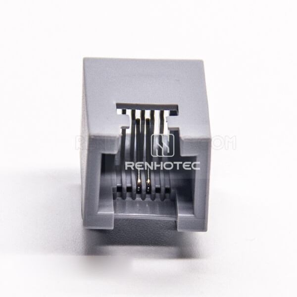
RHT-620-1239: six positions, two fitted contacts. Gray, unshielded, right-angle through-hole jack.
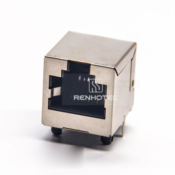
RHT-620-1201: eight positions, eight fitted contacts. Shielded, right-angle through-hole jack without LEDs.
Product photographs are shown at different scales. They identify the parts and housing styles; use each part’s drawing for dimensions.
On a loose cable plug, look for the row of metal contacts and the channels around them. On a jack, the contacts may sit deep inside the opening and be difficult to count from an angle. Use a clear front view or the part specification. Do not count the solder tails beneath a PCB jack as its mating contacts: shield tabs and other terminals can be present too.
Color is a poor identifier. RJ11 parts can be gray, black or clear, and RJ45 parts can have a plastic body or metal shield. The metal shell on the example above is a feature of that part, not a requirement that defines every RJ45 connector.
What 6P2C, 6P4C and 8P8C mean
P counts positions; C counts fitted contacts. A six-position housing with only two metal contacts is 6P2C. A 6P4C version has four contacts in a six-position body.
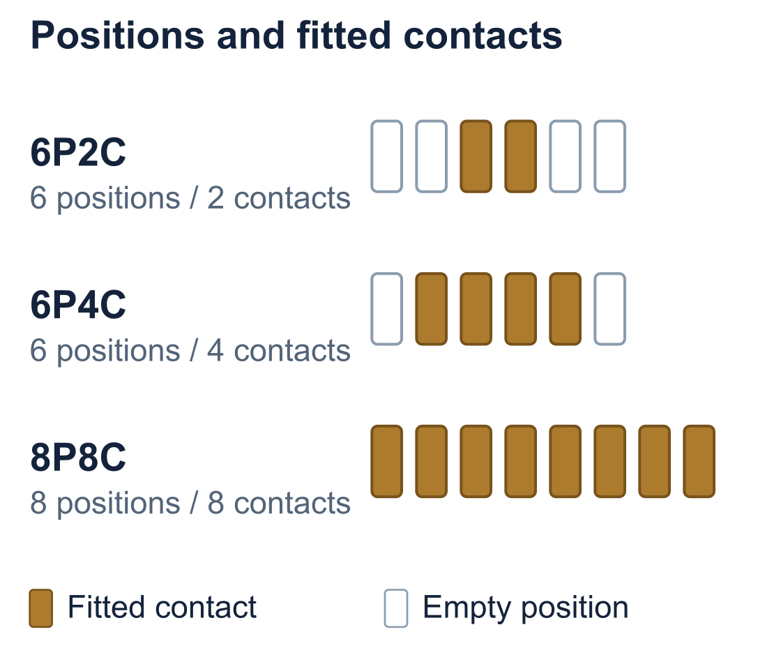
For a conventional single telephone line, the connection uses the central pair. That does not mean every product sold as RJ11 contains exactly two contacts. For example, TE Connectivity’s 5406904-1 product record calls the jack RJ11 and specifies six positions with four loaded contacts. Read the P/C specification when the number of available circuits matters.
The original Registered Jack system describes connection arrangements, including wiring and signals. Commercial connector names are often used more loosely; “RJ45” is the familiar name for the 8P8C Ethernet interface. Same Sky explains that naming distinction. For a purchase specification, write the connector family, P/C count and required circuit separately.
A 6P2C replacement cannot provide connections that require four fitted contacts. Conversely, a 6P4C cable may have unused conductors in a single-line installation. Contact availability tells you what can be connected; the equipment documentation tells you which contacts are used.
Read the port label before choosing a cable
An eight-position opening on a router might be an Ethernet port or a console port. A smaller opening might connect to the incoming DSL service or to an analog telephone. The device can contain several of these ports side by side.
| Port label | Typical function | What to check |
|---|---|---|
| PHONE / TEL | Analog telephone connection. | Whether the port is intended for a telephone or an incoming line. Follow the device’s connection diagram. |
| DSL / ADSL / VDSL | Broadband over a telephone pair. | The supported DSL service, port connector and cable supplied or specified for the modem. |
| LAN / Ethernet Ethernet WAN |
Network connection between Ethernet devices. | Port speed, required cable and any supported power functions. “WAN” describes a role; confirm the interface type. |
| CONSOLE / AUX | Equipment management, often serial on an RJ45-shaped port. | The manufacturer’s console interface and cable specification. |
Cisco’s console and AUX cable guide describes RJ45 connections used with serial terminals and adapters. Plugging that port into an Ethernet switch does not create a network connection.
When a wall outlet is unlabeled, inspect the cable’s far end and the installation record before connecting equipment. The faceplate shape cannot establish whether the outlet is wired for telephone, Ethernet or a proprietary system. If you cannot identify the service, have the connection traced.
Can you connect RJ11 to RJ45?
A smaller six-position plug may enter an eight-position socket. TE advises against this as a general connection method because the plug or socket contacts can be damaged. Insertion is not a useful compatibility test.
A purpose-built RJ11-to-RJ45 cable can still be correct for a particular installation. Check whether both endpoints use the same signal and the cable follows their specified wiring.
A passive adapter can change the connector arrangement
TP-Link’s Archer VR900v installation guide, page 17, specifies an RJ11-to-RJ45 cable between a DSL splitter and the modem router. Both ends belong to the DSL connection. This is an equipment-specific cable arrangement, not a way to connect a telephone service directly to an Ethernet port.
A modem provides the DSL-to-Ethernet connection
To connect a DSL service to a computer or an Ethernet-only router, use a compatible DSL modem or modem router. A passive connector adapter has no modem electronics. The service must terminate at the modem’s DSL interface; the Ethernet connection is on the modem’s LAN side.
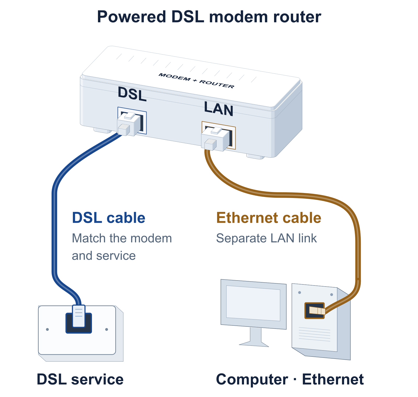
The same installation guide shows a separate Ethernet cable from the modem router’s LAN port to the computer. With a separate modem and router, follow their instructions for the Ethernet handoff and operating mode. Before buying an adapter, identify both device models and both port functions, then check the required end-to-end wiring.
Does RJ45 mean a faster connection?
There is no single data rate for an “RJ11 connection” or an “RJ45 connection.” A DSL link depends on the modem, service and line conditions. An Ethernet link depends on the equipment’s supported mode and the performance of the complete cable connection. Changing the plug does not change the service or add a new interface to the device.
For example, 1000BASE-T Gigabit Ethernet uses all four twisted pairs. A two-conductor telephone cord cannot become that link by adding eight-position plugs. Texas Instruments describes the four-pair Gigabit connection in section 2.2.2.1 of its reference design.
If you want to reuse cabling behind a telephone wall plate, first identify the cable construction, how it is routed and what is still connected to it. Suitable twisted-pair cable may be present, but an RJ11 faceplate provides no evidence of that. Have the cable and terminations checked against the intended Ethernet mode before changing the outlets.
For an Ethernet connection, our RJ45 pinout and wiring guide covers T568A/T568B, pair assignments and testing. Those wiring schemes do not define the contacts of a telephone, DSL or console port.
Choose a replacement for the cable or the board
For a damaged cable plug, match the connector and contact count to the equipment, then check that the plug accepts the cable’s conductor size and construction. For a PCB socket, the mating opening is only one part of the replacement decision.
- Compare the contact configuration and circuit. Record the full P/C count and the connections required by the equipment. For an Ethernet jack, also check whether magnetics are integrated or located elsewhere on the board.
- Compare the board drawing. Match signal-tail positions, mounting pegs, shield tabs and the through-hole or surface-mount arrangement. Two right-angle jacks can have different footprints.
- Check the enclosure fit. Compare the body height, entry direction and panel opening. Leave access for the plug latch and room for the cable to exit.
- Confirm the part’s electrical specification. Check the required signal performance, ratings, shielding and any LED connections. An 8P8C label alone does not establish Ethernet speed or PoE support.
Compare available contact configurations and mounting arrangements in the Renhotec modular connector range.
For help identifying a replacement, send the existing part marking, a clear view into the mating opening and a board-side photograph or drawing. Include the equipment’s port function.