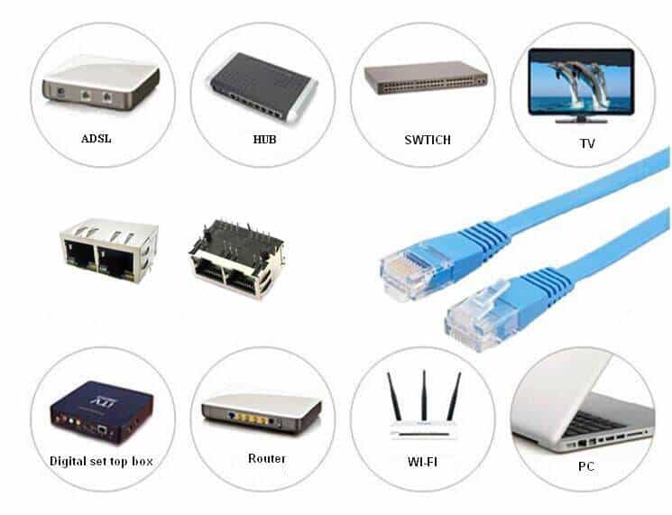
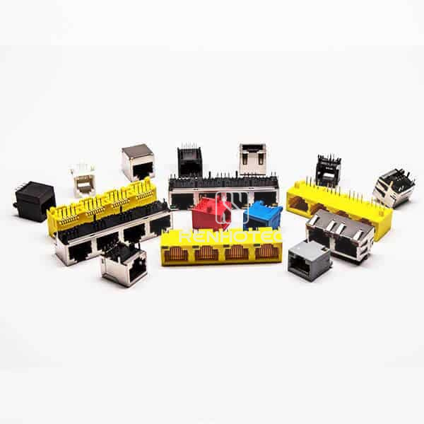
An Ethernet connection needs more than a connector that fits. Contact arrangement, PCB mounting, cable wiring and the electrical interface all need to match the equipment.
What does 8P8C mean?
The modular connector commonly called RJ45 in Ethernet applications has eight positions and eight contacts: 8P8C. P describes the positions in the connector, while C describes the contacts fitted. These numbers describe the connector structure; they do not by themselves define the circuit or the cable wiring.
Registered Jack designations refer to defined interfaces and wiring arrangements. The number after RJ is not the number of conductors. A six-position modular connector should therefore be identified by its contact arrangement and intended wiring, rather than assuming every 6P6C connector is RJ11.
Which jack configuration fits the equipment?
Check the mating plug and PCB drawing together. Entry direction and mounting orientation affect enclosure clearance; through-hole and surface-mount versions require different board layouts. For multi-port jacks, confirm the number and arrangement of ports as well as the overall dimensions.
Shielding, LEDs and integrated magnetics are separate options. A shielded housing needs an appropriate grounding arrangement. LED pin assignments and any integrated transformer circuit must match the host design; they cannot be established from the outside appearance alone.
T568A and T568B conductor order
T568A and T568B use different positions for the green and orange pairs. The table gives the colour assignment for pins 1 through 8. Confirm the pin-numbering view in the plug or jack drawing before terminating the cable.
| Pin | T568A | T568B |
|---|---|---|
| 1 | White/green | White/orange |
| 2 | Green | Orange |
| 3 | White/orange | White/green |
| 4 | Blue | Blue |
| 5 | White/blue | White/blue |
| 6 | Orange | Green |
| 7 | White/brown | White/brown |
| 8 | Brown | Brown |
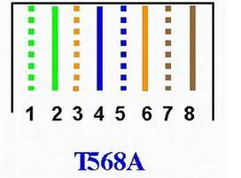
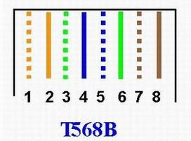
The colour scheme does not assign a universal transmit or receive direction. Equipment interfaces and supported Ethernet modes determine signal use. Whether a crossover cable is required also depends on the equipment, including support for Auto-MDIX; do not assume that every direct device-to-device link needs one.
Check the connection in its installation
For a network panel, controller or communications device, compare the panel opening, latch access, cable bend space and grounding path with the connector drawing. Confirm the required Ethernet capability and any power-delivery requirements using the documentation for the complete connector, cable and equipment combination.