
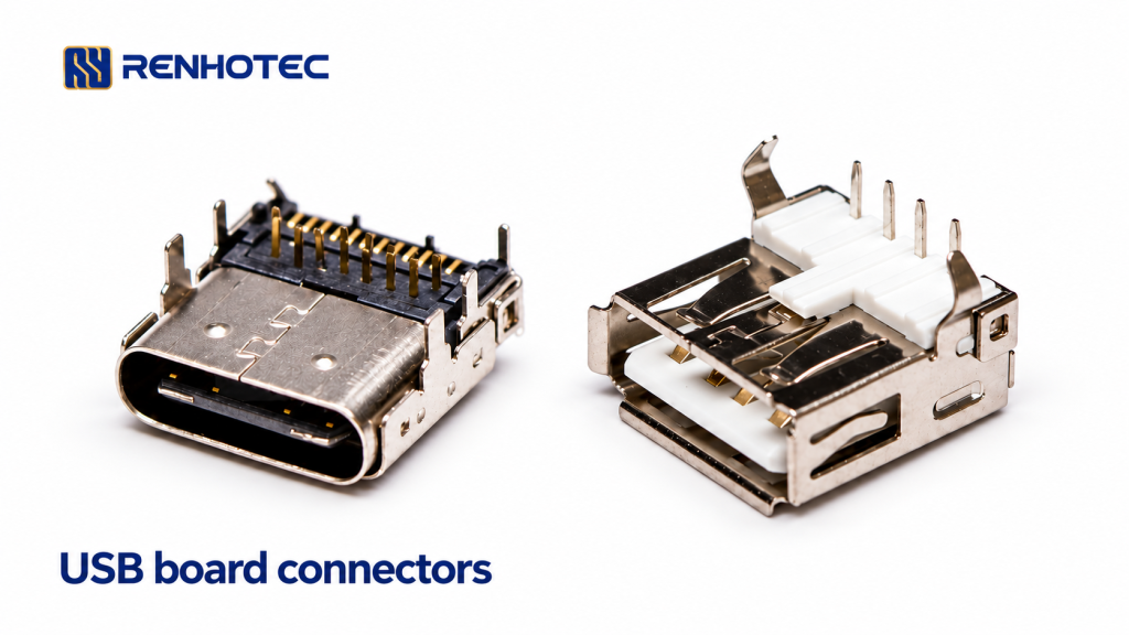
When choosing a USB connector for a PCB, start with the mating plug and the functions the device needs. Then match the connector’s contacts and mounting arrangement to the circuit board and enclosure. Two sockets can accept the same plug and still need different PCB layouts or support different functions.
For a replacement part, the existing footprint is a constraint. For a new design, define the interface requirements before choosing the footprint. The Renhotec USB connector range is a starting point for comparing forms and mounting options.
Separate the connector form from the required functions
Type-A, Type-B, Mini, Micro and Type-C identify connector forms. The form alone does not establish a supported data rate or power level. For a USB 2.0 or USB 3.0 connection, check the connector contacts, cable wiring and the host and device capabilities together.
USB Type-C provides a reversible mating interface. A Type-C port does not automatically provide a particular data speed, USB Power Delivery or video output. USB-IF’s language guidelines distinguish the connector specification from data performance and USB Power Delivery. A USB 2.0 Type-C implementation can support USB Power Delivery while omitting the contacts needed for faster USB data operation.
Write the intended data interface and power role separately. Include the required data rate, whether the device supplies or receives power, and its operating voltage and current. If video is required, name the intended display interface and check the supporting equipment and cable or adapter. A connector’s current rating does not establish the functions of the complete device.
Read the contact definition before choosing a pin count
A search for a “12-pin Type-C connector” can narrow a catalogue, but it is not enough to select a part. Ask what the listed number counts, and compare the drawing’s contact definition with the circuit schematic. The mating interface, solder tails and shell fixing points serve different purposes.
For a USB 2.0 data connection, the drawing must identify the required data contacts as well as the power and configuration contacts applicable to the design. For a faster data interface or a display connection, check its additional signal requirements with the system design. Do not assign signal functions from a photograph or assume that a higher contact count proves a particular speed.
Use the exact part number and drawing revision when comparing alternatives. If a supplier provides a PCB layout without a contact-function table, request that table before approving the electrical replacement.
Compare the PCB attachment and the mating position
“PCB mount” leaves several decisions open. Surface-mount contacts solder to pads; through-hole contacts pass through the board. A connector can combine different attachment methods, so check the signal contacts and shell retention separately. Molex’s Type-C range, for example, distinguishes top-mount, mid-mount and vertical options. Those are mechanical choices within the connector family, not interchangeable footprints.
- Board footprint: compare pad positions, hole sizes and spacing, locating features and any board cut-out. Use the specified viewing direction; a mating-face view is not a PCB solder-side view.
- Position in the enclosure: check the mating height from the board datum, distance from the board edge and connector body projection. The opening must leave room for the plug housing, not only the metal mating end.
- Assembly: match the contact and shell attachments to the intended solder process and board thickness. “Through hole” in a filter does not tell you whether it describes the electrical contacts, retention tabs or both.
- Retention and access: allow space to insert and remove the cable, and assess how mating loads reach the board or enclosure. Use the selected part’s mechanical specification for retention and durability requirements.
Use the product page to build a mechanical shortlist
RHT-692-1316 is a USB 2.0 Type-A female connector with a right-angle orientation and through-hole PCB mounting. It is a candidate when the design calls for that mating interface and mounting arrangement. Its hole pattern, board-edge position and enclosure clearance still need to match the design.
For a Type-C mating interface, RHT-692-1263 is a female, right-angle PCB connector whose product page lists DIP and SMT. Compare its pads and holes against the board drawing. The published mounting information does not establish a data rate, video function or USB Power Delivery capability for the selected assembly.
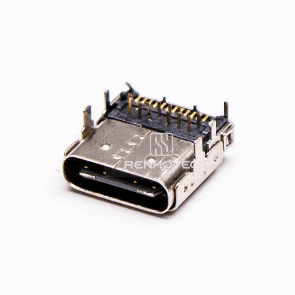
These two parts serve different mating interfaces. They illustrate how form, orientation and mounting narrow the choice; they are not drop-in replacements for one another.
Send a requirement sheet with the selected part
For a new design, send the interface requirements with the PCB and enclosure drawings. For a replacement, include the existing part number, its drawing revision and photographs of both the mating face and board attachment. A useful inquiry contains the following:
| Item | Information to supply |
|---|---|
| Connection | Plug or receptacle; connector form at this end; mating cable or equipment; required data interface and rate. |
| Power and other functions | Supply or receive power; operating voltage and current; USB Power Delivery or display requirements where needed. |
| PCB and enclosure | Board thickness, footprint and viewing direction; mounting height and board-edge datum; enclosure opening and available plug clearance. |
| Assembly and service | Solder process; shell retention; operating environment; expected mating cycles; shielding or sealing requirements. |
| Part approval | Candidate part number and drawing revision; required electrical ratings and test criteria; sample quantity and production quantity. |
Use the selected part specification for current rating, contact resistance, insulation resistance, dielectric withstand voltage and operating temperature. These are different characteristics. In particular, a dielectric withstand test voltage is not the device’s normal operating voltage.
If the requirement includes a cable assembly, add both connector ends, cable length, wiring, required data capability and the installation route. Find the candidate in the USB connector range, then open its product page to send an inquiry that identifies both the part and the intended connection.