
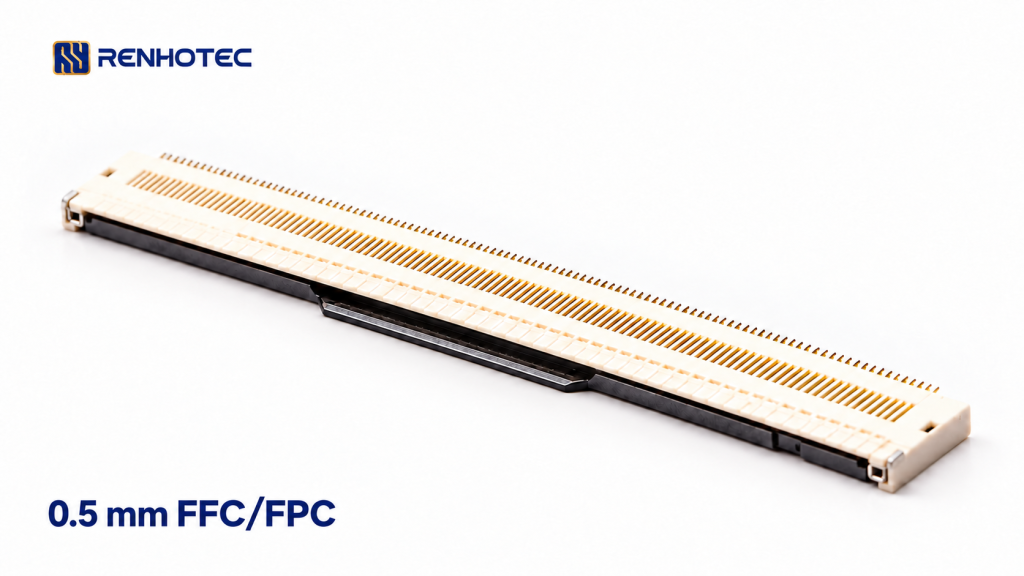
A 0.5 mm pitch match is a useful first filter when replacing an FFC/FPC connector. The replacement must also suit the cable’s contact face and finished mating-end thickness, leave room for insertion and locking, and fit the PCB lands. Match the contact count at the start; a 24-position and a 12-position connector are different configurations.
For an existing board, compare the original connector drawing, the cable drawing and the proposed replacement drawing together. If you are designing a new board, you can change the footprint, but the connector and cable still need a compatible mating interface.
Follow the exposed contacts through the connection
Locate the exposed conductors at the cable end, then find the connector’s contact surfaces in its section view. With the cable in its intended route, those surfaces must meet. A photograph of the closed lock or the colour of the cable stiffener does not establish the contact side.
Hirose’s FH12 operating instructions show the distinction clearly: for its horizontal bottom-contact version, exposed cable conductors face the PCB; for the top-contact version, they face away from it. Use the drawing’s mounting surface and insertion view as references, particularly if the board is upside down in the enclosure.
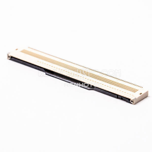
In the Renhotec range, RHT-616-0110 provides a bottom-contact, front-flip starting point for a 96-position requirement. Its product page identifies that configuration; it does not establish a compatible cable thickness or a drop-in replacement for another manufacturer’s connector.
Also follow the cable to its other end. FFC listings may describe the exposed contacts as being on the same side or opposite sides. For example, Molex 153660537 identifies its layout as Type A, same side. That is a cable-end arrangement, while top or bottom contact describes the board connector. Record the required arrangement at both ends and verify conductor numbering against the circuit drawings before changing either component.
Compare the finished mating end, including its tolerance
Use the thickness at the portion that enters the connector, including the stiffener where specified. The thin flexible span between the two ends can have a different construction. The mating-end drawing should also define the exposed contact length, cable width and any locating or retention features.
Even two connector families described as 0.5 mm pitch and suitable for a nominal 0.30 mm cable can specify different thickness tolerances:
| Manufacturer example | Specified FPC/FFC thickness |
|---|---|
| Hirose FH12 | 0.30 ±0.05 mm 0.25 to 0.35 mm |
| Hirose TF07V | 0.30 ±0.03 mm 0.27 to 0.33 mm |
A finished end measuring 0.34 mm falls within the first stated thickness interval and outside the second. This checks only that one dimension; it does not prove a cable mates with either family. These values are specific Hirose examples, not Renhotec cable specifications.
For a replacement, compare the cable’s permitted minimum and maximum thickness with the proposed connector’s requirement. A nominal value or one sample measurement cannot establish that every cable in the specified tolerance will fit. Do the same for the contact length and insertion depth so the exposed conductors reach the intended contact area.
Leave room to insert the cable and operate the lock
Front-flip, back-flip and slider describe different actuator arrangements. ZIF identifies a zero-insertion-force mechanism; it does not specify the contact side or PCB footprint. Molex’s FFC/FPC range treats pitch, actuator style and circuit count as separate selection dimensions and includes both ZIF and non-ZIF designs.
For a 0.5 mm, 12-position dual-contact ZIF configuration, see RHT-616-0113. The 0.5 mm RHT-616-0120 is listed as a 24-position, horizontal, dual-contact socket without a lock. These are different configurations to narrow by requirement, not an interchangeable pair.
On an assembled board, check the actuator in its open position as well as its closed position. Allow access from the actual assembly direction, including the cable’s insertion path and the space needed to release it during service. A connector that clears the enclosure when closed may still be impossible to operate beside a tall component.
Follow the selected part’s handling instructions. For example, the FH12 instructions call for full, straight insertion before closing the actuator and warn against forcing the lock on a partly or diagonally inserted cable. Do not treat a difficult latch as proof that the cable simply needs more pressure.
Match the PCB footprint before calling it a replacement
Compare both connector drawings in the same view and orientation, with pin 1 and the cable-entry edge aligned. A mating pitch of 0.5 mm does not define the complete solder-pad pattern. Check these features against the actual board:
- Signal-pad positions, widths and lengths, including any staggered or offset terminal rows.
- Hold-down tabs, mounting pads and locating holes, where present.
- Body outline, seating position and the cable-entry location relative to the pads.
- Open-actuator clearance, closed height and space for the cable’s intended route.
Keep mating geometry and board geometry separate while making this comparison. For example, Molex’s 501951 drawing provides an insertion-depth view and separate recommended cable and PCB dimensions. Use the corresponding drawings for the exact Renhotec part and your cable; a footprint from a similarly named family is insufficient.
If the cable interface fits but the board lands do not, the candidate requires a PCB layout change. If the board lands fit but the cable contact side or mating-end dimensions differ, the existing cable cannot be assumed to work. Only after both interfaces match should you proceed to the electrical ratings, assembly process and sample evaluation required for the equipment.
Use the Renhotec FPC/FFC connector range to narrow the contact count, pitch and mechanism. For a RHT-616-0110 inquiry, attach the cable-end drawing and the PCB land pattern, identify the original connector if replacing one, and show the available actuator clearance. Include the required current, voltage and operating conditions so the candidate can be assessed for the complete connection.