
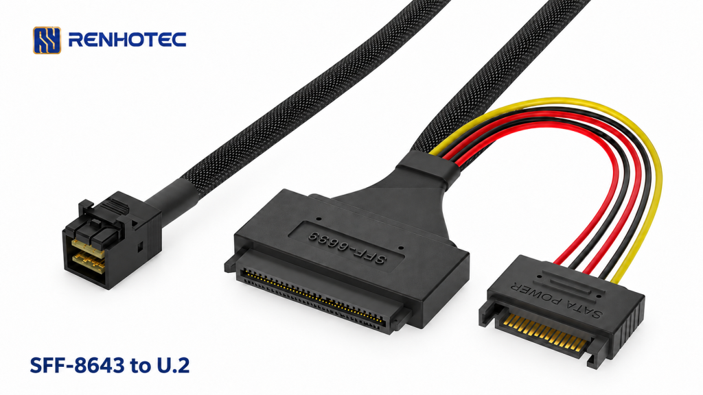
Renhotec RHT-726-5004 connects a Mini-SAS HD SFF-8643 end to one U.2 SFF-8639 drive end, with a separate 15-pin power lead and mounting ears at the U.2 housing. Consider it for a U.2 NVMe SSD only when the host port carries a compatible PCIe link and its pin assignment matches this assembly.
Read the host port’s electrical assignment
| What the host manual says | Decision for RHT-726-5004 |
|---|---|
| PCIe/NVMe support, with a compatible x4 link and documented pin assignment | Proceed to compare the cable signal table, SSD power requirements and mounting geometry. |
| SAS/SATA support only | This assembly does not convert that port into a PCIe/NVMe connection. |
| Tri-mode or switchable protocol | Check the controller’s exact port mode and approved NVMe cable wiring; the label alone is insufficient. |
| Only the SFF-8643 connector name is given | Obtain the port’s electrical assignment before selecting the cable. |
Look up the actual connector label printed on the board, then locate its lane and sideband assignments in the equipment documentation. If the manual refers to a specific cable part number, use its drawing as the comparison reference. Do not substitute based on matching end names alone.
SNIA SFF-9402 Rev 1.1, section 5 describes incompatible PCIe and legacy SAS/SATA implementations using the same SFF-8643 connector form. Ask the equipment supplier for the port assignment if the manual gives only the connector name.
Compare clock and reset as well as data lanes
The RHT-726-5004 drawing, R1.0 dated 17 June 2024 labels the U.2 end P0, the SFF-8643 end P1, and the power input P2. Its signal table includes four PCIe transmit/receive lane groups and the following clock and reset connections:
| Signal labels in R1.0 | P1 · SFF-8643 contact | P0 · U.2 contact |
|---|---|---|
| CLK+ → CLOCK+ | A1 | E7 |
| CLK− → CLOCK− | A2 | E8 |
| RST → RST | B1 | E5 |
These entries let you ask a concrete question: does the host’s SFF-8643 port assign those contacts to the required clock and reset signals? Compare the remaining lane, ground and management connections in the full drawing as well. A match on these three rows alone is insufficient to approve the assembly.
The contact names above are copied from this cable’s drawing. They are not a universal SFF-8643 pinout, and the photograph is not a contact-counting reference. Use the connector views and orientation in the drawing when comparing documents.
Allow space for the U.2 ears and power lead
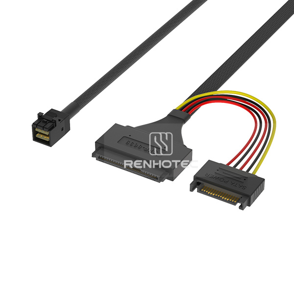
The R1.0 drawing gives a 60 mm overall span across the mounting ears and a 42.6 mm housing span. The 60 mm dimension runs between the outer ends of the ears; it is not a hole-centre dimension. The published sheet does not dimension the mounting-hole pitch or diameter. Obtain those details for the proposed supply version before drilling a bracket or choosing fasteners.
The assembly length is shown as 500 ±20 mm between the indicated datums. Measure the route from the host socket to the installed U.2 connector, allowing for the connector bodies, release access and the cable supplier’s bend limits. That dimension does not specify the free reach of the colored-wire power branch.
Check P2 against the SSD’s power requirements and the approved system supply. Confirm the required rails, current capacity and power-contact assignment; connecting the SFF-8643 signal end alone does not supply the separate drive-power input shown in this assembly. Follow the equipment’s service procedure for installation and removal. The cable’s connector type does not establish hot-swap support.
Request a match to your port and carrier
Send the host model, revision and port label, the port pinout or approved cable drawing, and the U.2 SSD model with your RHT-726-5004 configuration request. Include the carrier’s mounting drawing, required routed length and the power-feed location. Specify the target PCIe generation and ask for the assembly rating at the proposed length for that host and SSD combination.
If the host uses SlimSAS, OCuLink or another interface, start with the U.2 cable range and select the appropriate host end. Keep the SSD, power and carrier requirements with that request so a change of host connector does not leave the drive installation unspecified.