
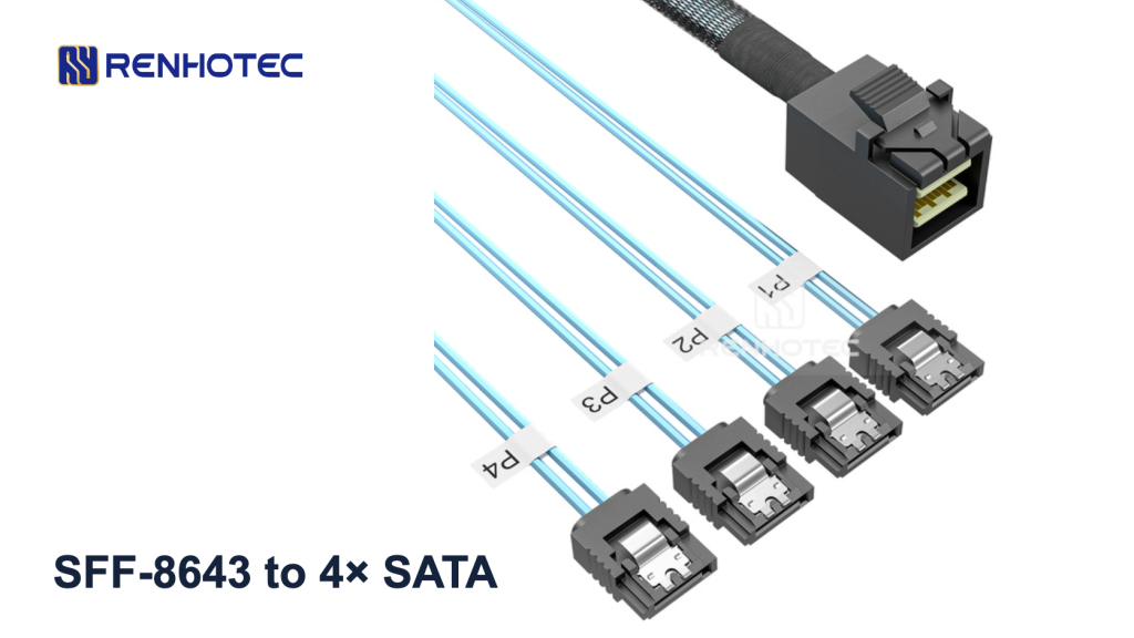
Shortlist Renhotec RHT-726-3007 when you need to connect one internal SFF-8643 SAS/SATA controller port to four individual SATA drive data ports. The controller must support SATA drives on that port, and each drive needs its own power connection. The published R1.0 drawing shows one Mini-SAS HD 4i end, four SATA 7-pin ends and a length dimension of 500 ±20 mm.
That makes it a candidate for a compact, direct-to-drive storage layout. Check the port role and the route to the furthest drive before choosing it: an SFF-8643 socket can also be used in configurations that require different wiring.
Check the controller and drive ends first
| Your connection | Selection decision | What to verify |
|---|---|---|
| SFF-8643 SAS/SATA host port → individual SATA drives | Shortlist RHT-726-3007. | The controller manual permits SATA drives on this port; the cable reaches all required drive positions. |
| Four motherboard SATA ports → an SFF-8643 backplane | Specify a reverse breakout assembly. | The backplane model and its required wiring. RHT-726-3007 is not the reverse configuration. |
| An SFF-8643 port carrying PCIe → an NVMe drive | Choose a cable for that PCIe port and drive interface. | The board’s port assignment and the exact drive connector. Four SATA ends do not provide a U.2 connection. |
| A SAS drive or a drive backplane with a different connector | Choose the required drive-side interface. | The connector on the drive or backplane; these four ends are SATA 7-pin data connectors. |
The wiring in the RHT-726-3007 drawing, R1.0 dated 17 June 2024 is consistent with a forward breakout: controller transmit pairs reach the SATA device receive pairs, and controller receive pairs reach device transmit pairs. This is a comparison of the published drawing with the SAS/SATA signal assignments, not a compatibility test on a named controller.
SNIA’s SFF-9402 Rev 1.1 distinguishes SAS/SATA and PCIe uses of SFF-8643. Use the controller or motherboard manual to identify the signals on your socket. If you need different connector ends or an angled configuration, compare the Mini-SAS HD cable range before settling on this part.
Plan four data connections and separate drive power
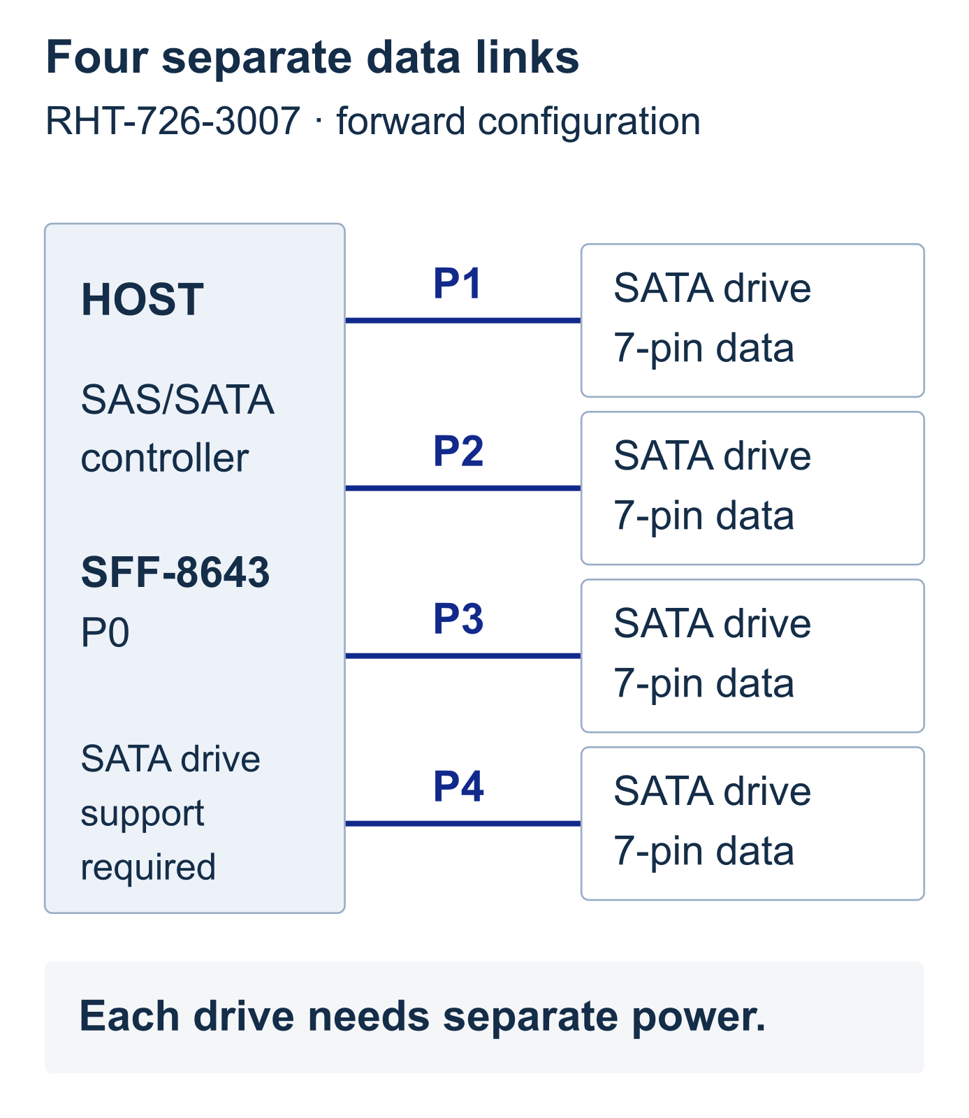
Connect the four 7-pin ends to the drives’ SATA data ports. Provide power through each drive’s separate power connector, following the drive and system specifications. The cable drawing contains no drive-power connector, so a data connection alone will not power a drive.
The four branches correspond to four controller links. The assembly does not turn a single SATA host port into four ports. Check the controller’s supported drive configuration and negotiated link rate separately; the Mini-SAS HD connector name does not establish a system throughput figure.
Use P1–P4 to trace the branches
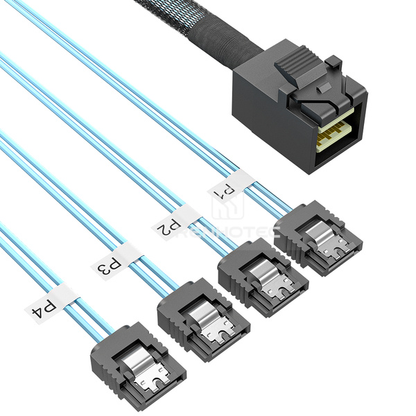
The drawing calls the Mini-SAS HD end P0 and the four SATA ends P1–P4. The table below relates those branches to the SAS/SATA controller lane assignments in SFF-9402. “PHY” identifies a physical controller link.
| SATA branch label | Controller link at P0 | P0 signal contacts traced in the drawing |
|---|---|---|
| P1 | PHY 0 | B4/B5 and D4/D5 |
| P2 | PHY 1 | A4/A5 and C4/C5 |
| P3 | PHY 2 | B7/B8 and D7/D8 |
| P4 | PHY 3 | A7/A8 and C7/C8 |
This mapping applies to the published R1.0 cable drawing and the SAS/SATA controller pin assignment. Contact IDs in the table are drawing references; use the PDF’s views and full pin-assignment table for a wiring check. Do not count contacts from the product photograph.
Keep a record of which cable label reaches each drive bay and drive serial number. P1 does not promise “Disk 1” in firmware or the operating system; the software naming and enclosure arrangement must be checked on the actual system.
Check the 500 mm configuration against your route
The drawing marks 500 ±20 mm between its indicated length datums and shows a separate 290 REF dimension along the sleeved section. Use those dimension lines when comparing the assembly with your chassis. The 290 REF callout is a reference dimension, and 500 mm is not the available reach of each loose branch after the sleeve ends.
Trace the route from the controller connector, around chassis obstructions, to the furthest drive. Allow space for the connector bodies, the cable exit and access to the retention clips. Check the nearest drive too: excess cable still needs somewhere to sit without pressing against a fan, cover or adjacent connector.
For widely separated bays or a tight turn at the host connector, send a marked chassis view with the required route and branch reach. Ask Renhotec to confirm a suitable length or orientation against an applicable drawing. Do not assume another length uses the same branch arrangement or that a sharp bend will make this one fit.
Specify the configuration for your inquiry
If the port roles, drive interfaces and route match, use the RHT-726-3007 product page to review the listed configuration and submit an inquiry with:
- The controller or motherboard model and the SFF-8643 port designation.
- The SATA drive models, quantity and drive-bay arrangement.
- Your routed length, required branch reach and any connector-clearance limits.
- The separate drive-power arrangement.
- The requested quantity and the drawing revision to be confirmed for supply.
For a repeat build, retain the agreed drawing with the order. The public R1.0 drawing is the basis of this guide; the supplied configuration and any requested change should be confirmed against that order’s drawing.
Technical references: RHT-726-3007 R1.0 drawing; SNIA SFF-9402 Rev 1.1, §5 and Table 8-1; Viking Technology SATA SSD manual, Rev G, Table 4-1 for SATA device transmit/receive definitions.