
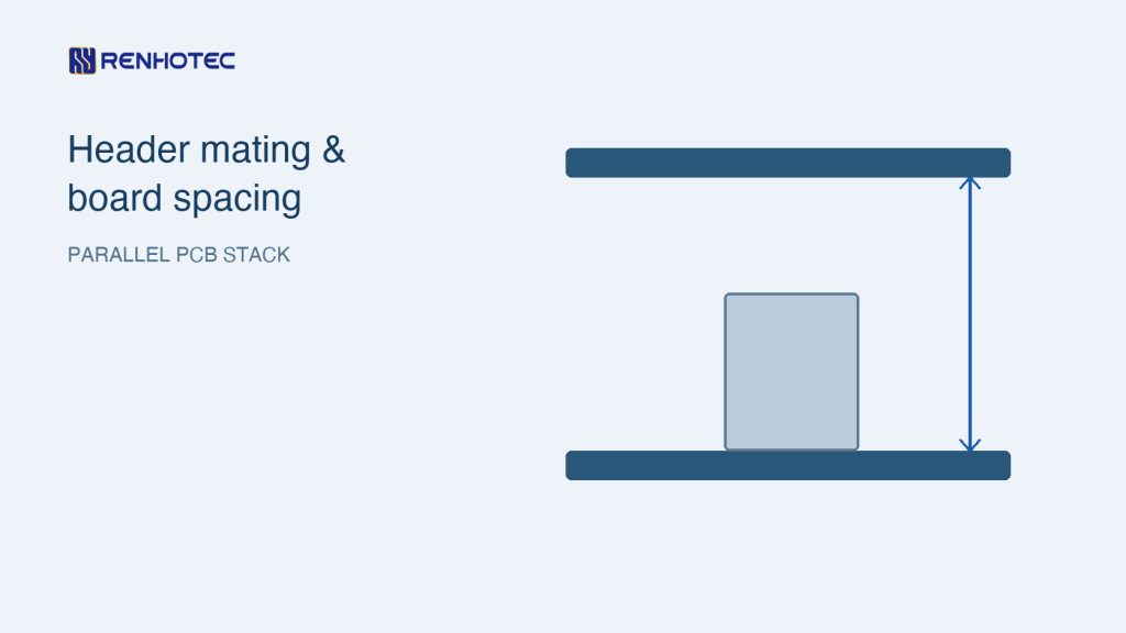
A pin header and a female header can connect two parallel circuit boards, but matching pitch and position count is only the beginning. The pins must fit the socket contacts, the two PCB footprints must align, and the assembled board spacing must keep the contacts within their specified engagement range.
Start with the space your assembly needs, then compare drawings for both halves. If the pair has no confirmed mating or engagement information, treat it as a candidate—not a proven combination.
Start with the two board surfaces
For a parallel stack, define the distance between the two facing PCB surfaces after assembly. This is commonly called the board-to-board or stack height; check the reference surfaces in the drawing because manufacturers may dimension a product from another datum. EDAC’s board-to-board guide describes stack height as the distance between the board surfaces when mated.

Measure the tallest component, soldered features and any insulation on the facing sides, then allow the clearance required by your design and assembly process. Check enclosure limits above and below the boards as well. A connector body’s listed height alone is not the finished spacing: both halves and their engagement affect the result.
For a new design, choose a pair that provides an appropriate spacing and permits the required clearance. For a replacement, the existing standoffs, board positions and enclosure can fix the available spacing before a connector is chosen.
Match the mating interface, not just the pitch
Pitch is the centre-to-centre distance between adjacent positions. It narrows the candidates, but it does not establish that a particular pin will fit a particular socket. Compare the exact drawings and, where available, the manufacturer’s identified mating parts:
- Rows and positions: match the number of rows, positions per row and the spacing between rows. Check whether every position is populated or a position is omitted for keying.
- Pin and socket geometry: compare pin shape, mating-section dimensions and length with the socket’s accepted mating dimensions. Check the applicable tolerances, not just nominal figures.
- Alignment and orientation: identify pin 1 from each drawing in a consistent view. Unshrouded headers may allow a reversed or offset assembly; provide a suitable way to identify the correct orientation.
- Engagement: verify the permitted mating depth or the specified mated height for that pair. A pin that enters a socket is not evidence that engagement remains adequate at the installed spacing.
For a concrete example of why pin shape matters, E-tec’s female header datasheet specifies a 2.54 mm pitch and mating with 0.64 mm square pin headers. Those dimensions apply to that example; they do not establish the accepted pin size for a Renhotec socket.
The Renhotec board-to-board range includes pin and female headers with different arrangements and mounting styles. Use the listing to narrow candidates; obtain the drawings and confirm the intended pair before committing a footprint or ordering a replacement.
Check engagement across the whole assembly
Compare the connector pair’s allowed mated condition with the complete mechanical stack: PCB thickness and flatness, connector seating, solder joints, standoff height and enclosure tolerances. Check the limits at both ends of the stack, not only the nominal dimension. The result must avoid both insufficient engagement and forcing the parts past their allowed position.
Do not assume that two housing heights can simply be added. Some contacts continue to engage over a specified range; other products define a seated condition. For its own board-to-board range, GCT illustrates different stacking arrangements and treats the connector combination as part of the height calculation. The selected pair’s drawings and application instructions control the actual limits.
Standoffs and fasteners also need their own design check. They should hold the boards in the intended position without pulling the connector away from its permitted engagement or forcing it beyond it. Where multiple connectors join the same boards, include their relative alignment and assembly sequence in the mechanical review.
Separate mating geometry from each PCB footprint
The interface between the header and socket is one check; the interface between each connector and its PCB is another. On each drawing, identify the recommended land pattern or hole layout, the board side and the viewing direction. Align pin 1 and the board edge before comparing an existing footprint.
| Check | Why it matters |
|---|---|
| Pitch and row spacing | Both mating contacts and board holes or pads must align with their respective drawings. |
| Through-hole or SMT | Each half needs the correct hole or land pattern and a suitable assembly process. |
| Pin 1 and board side | A mirrored view or a connector mounted on the opposite side can reverse the apparent layout. |
| Body, tabs and nearby parts | Connector outline and any retention features must clear the board and enclosure. |
A replacement may match the contact grid but still need a different pad shape, hole size or body clearance. For a new PCB, use the exact connector revision and the manufacturer’s recommended layout; do not transfer a footprint from a similar-looking part without comparison.
Finish with electrical and service requirements
After the mechanical pair is identified, check the selected contacts’ current and voltage ratings, operating conditions and mating durability against the equipment requirements. If the link carries fast signals, use a connector system with suitable documented signal-integrity information for that design; pitch alone does not establish a data-rate capability.
Allow a straight assembly path and enough access to separate the boards without prying on the contacts or solder joints. Consider board support, vibration, adjacent components and the number of expected service cycles. Follow the selected manufacturer’s handling and application guidance and validate the completed assembly under the conditions required by the project.
To review candidates in the pin header and female header ranges, prepare the row and position count, pitch, PCB layouts, required board spacing and tolerances, current and signal requirements, and the installation environment. For a replacement, include both original part numbers and drawings if available; for a new pair, request the mating and engagement details for the exact candidates.