
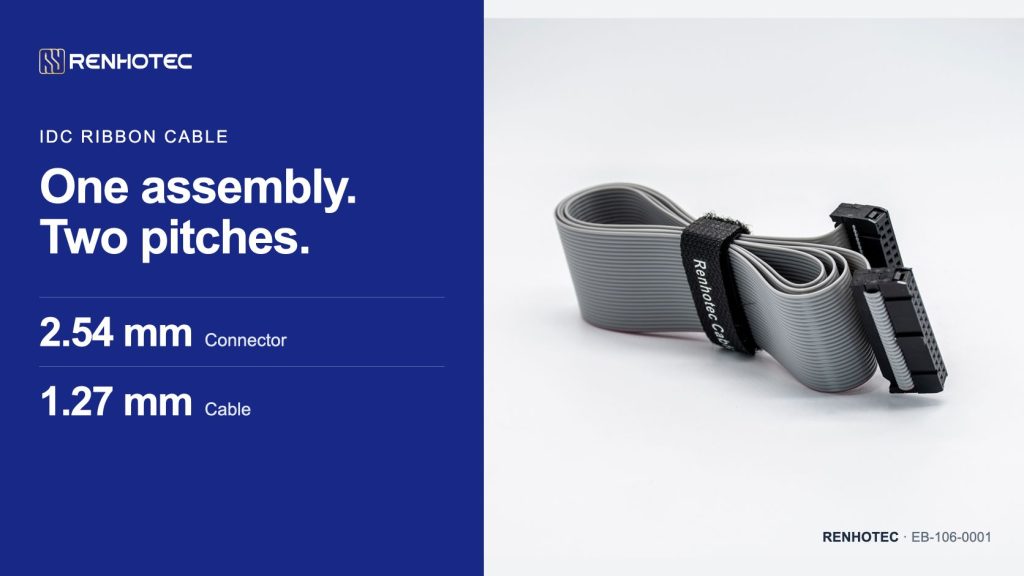
A ribbon cable can have conductors spaced 1.27 mm apart while its IDC (insulation-displacement) socket mates with a 2.54 mm header. Both dimensions can be correct. They describe different parts of the connection: the spacing of wires in the cable and the spacing of contacts along a connector row.
For a replacement, record both dimensions before ordering. “10-way IDC, 1.27 mm” leaves too much unresolved: does 1.27 mm describe the cable or the mating interface? The checks below apply to conventional two-row ribbon-cable IDC systems. Other IDC constructions need their own drawings.
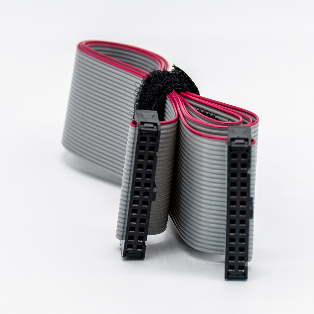
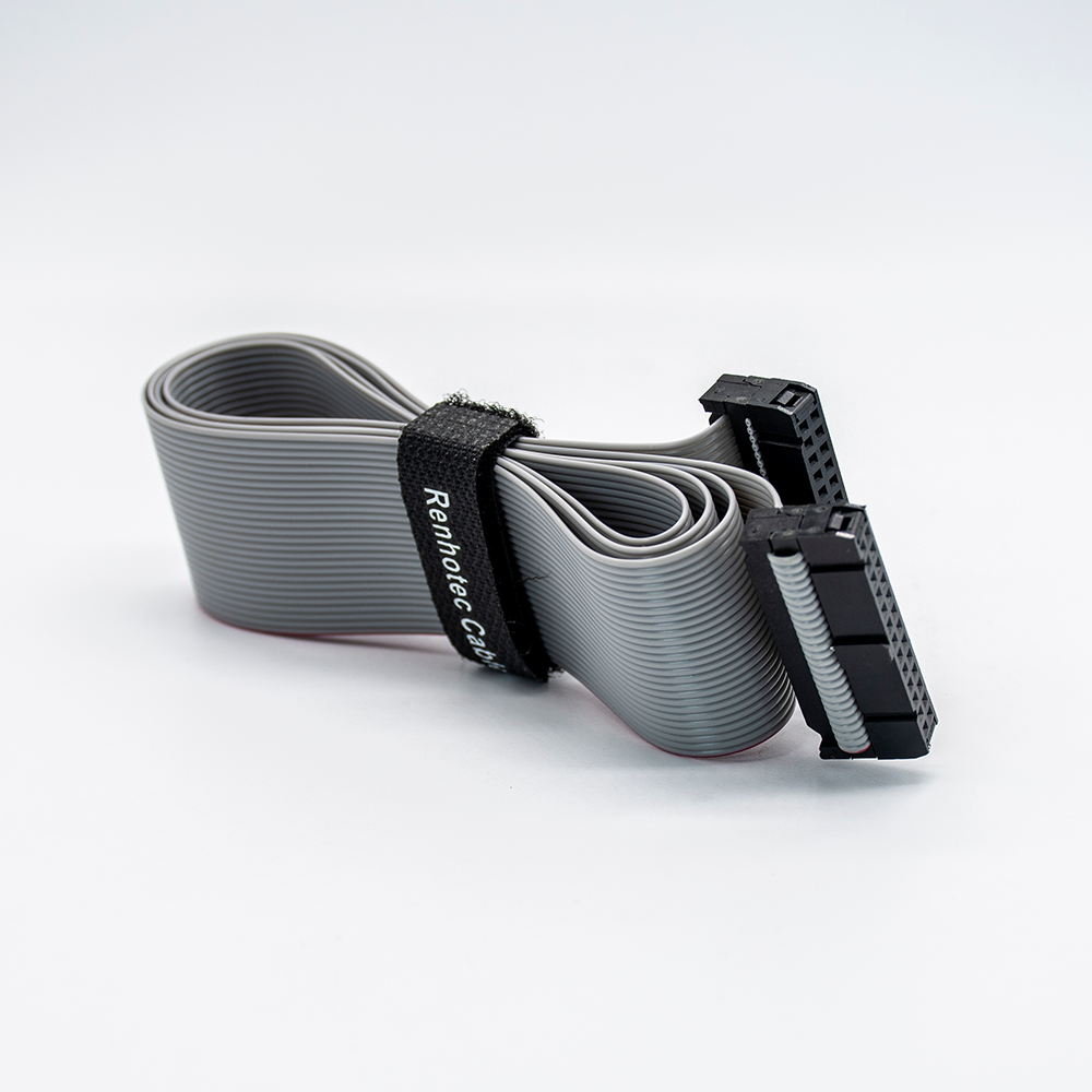
A Renhotec assembly example
EB-106-0001
2.54 mm
IDC connector pitch.
1.27 mm
Ribbon cable conductor pitch.
The product specification lists both dimensions separately for this 26-conductor assembly with two 2 × 13 sockets.
Identify the three distances first
Start with the mating face, where the socket meets the board header. Measure between adjacent contact centres in the same row. Then measure between the two row centre lines. Finally, inspect the cable separately and measure between adjacent conductor centres.
- Contact pitch
- Centre-to-centre spacing along one row of mating contacts.
- Row spacing
- Distance between the centre lines of the two contact rows.
- Cable pitch
- Centre-to-centre spacing between adjacent conductors in the ribbon.
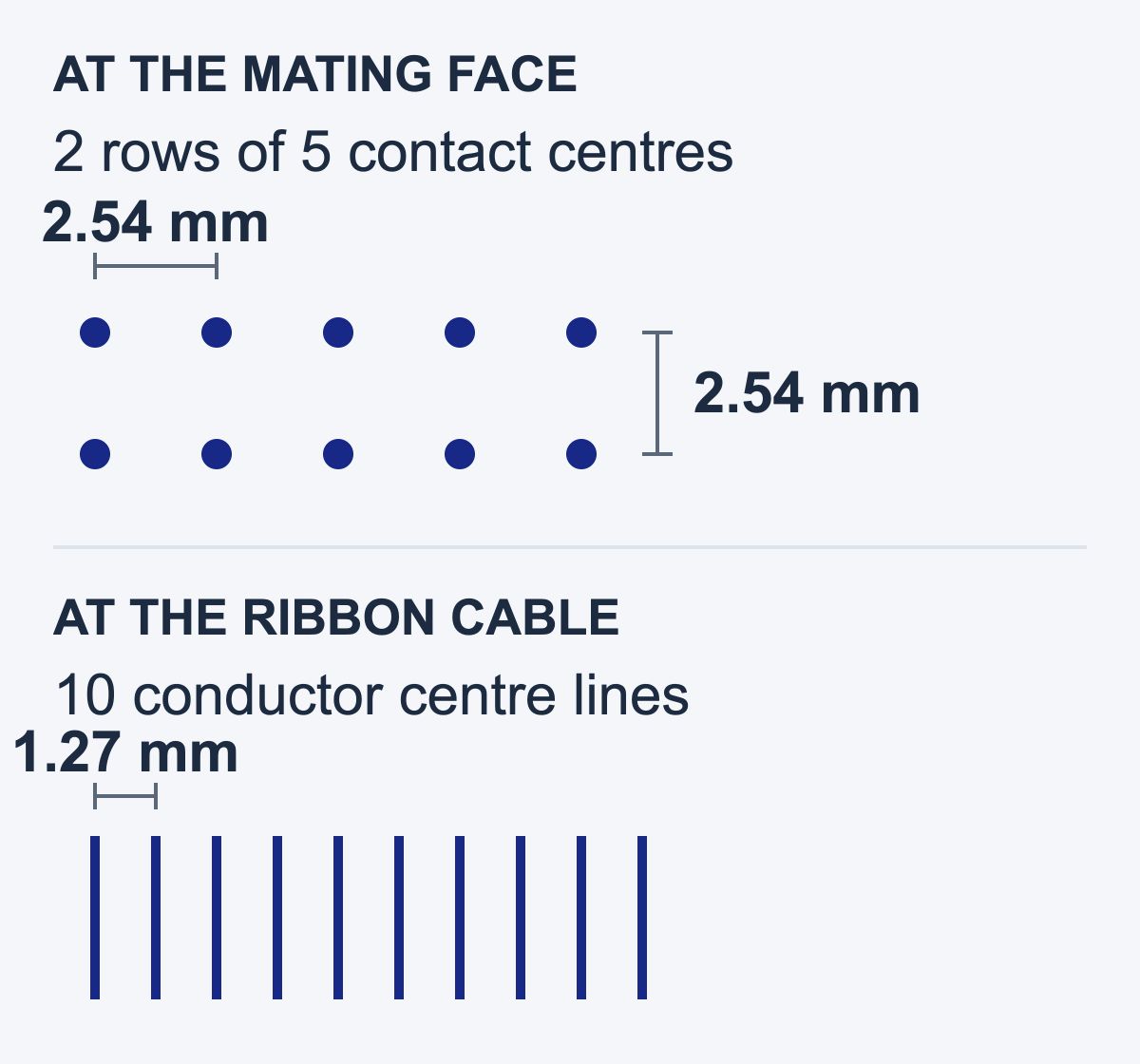
The 3M 891 series drawing, sheets 1–2, provides a concrete example: a 0.100 × 0.100 inch mating layout, intended for 0.050 inch pitch cable. Converted to millimetres, that is 2.54 × 2.54 mm at the connector and 1.27 mm at the cable.
Why the cable pitch can be half the contact pitch
In this arrangement, the terminations serving the two contact rows are staggered across the ribbon. Adjacent conductors connect into alternating rows, so conductors serving the same row are two cable intervals apart. Two intervals of 1.27 mm give 2.54 mm.
That relationship explains the dimensions. It does not identify pin 1, assign signal names or determine which way either connector faces. Use the selected connector’s termination drawing and the equipment wiring documentation for those decisions.
A socket sold as having a 1.27 mm mating pitch is a different size from a 2.54 mm socket that accepts 1.27 mm cable. The word “pitch” needs a measurement reference whenever it appears on a purchase specification.
A 10-position example you can measure
A two-row, 10-position connector has five positions per row. There are four intervals between the first and last contact centres of either row. A ten-conductor cable has nine intervals between its outermost conductor centres.
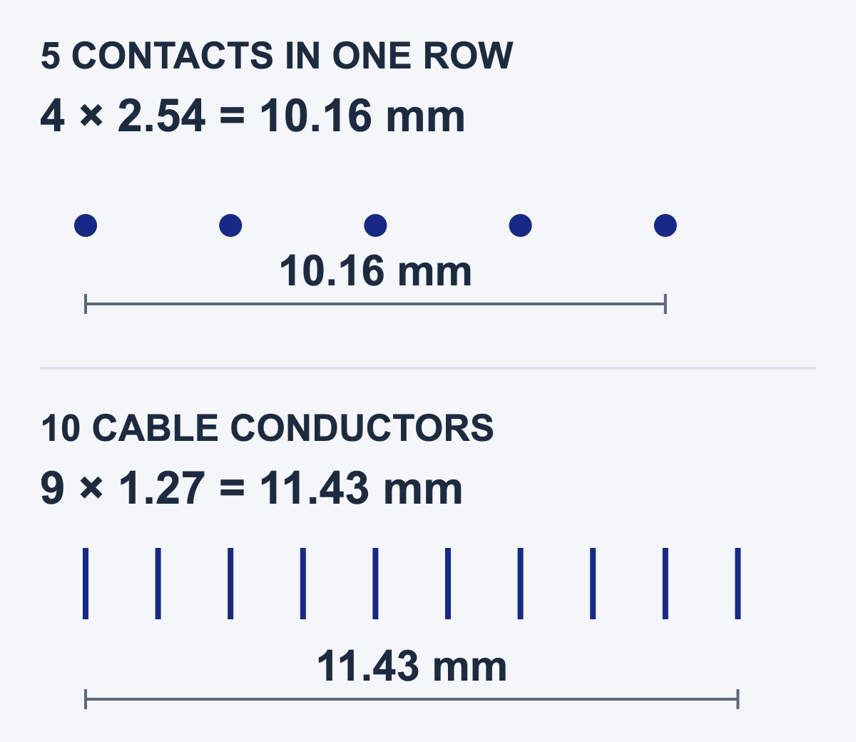
If the first-to-last contact span is approximately 10.16 mm across five positions, divide by four to estimate the pitch. Do the same independently on the cable: an approximately 11.43 mm span across ten conductor centres gives 11.43 ÷ 9 = 1.27 mm. Measure across as many clearly visible intervals as practical, without bending pins or compressing the cable.
Outside edges need different treatment. In the 3M 3365 cable drawing, sheet 2, the ten-conductor version has a nominal overall width of 12.70 mm and an outermost-conductor centre span of 11.43 mm. The insulation margins account for the difference. Dividing overall width by nine would give the wrong pitch.
These calculations help identify a likely family. They do not replace the dimensional tolerances in a drawing. A damaged sample, an indistinct conductor centre or a perspective photograph may be insufficient to distinguish close dimensions.
Use the connector family to select the cable
There are smaller IDC interfaces with smaller cable spacing. E-tec lists the following combinations for its IDC female-header families. The table is useful for understanding the labels; it is not a cross-brand compatibility list.
| Mating pitch | Cable pitch | Series reference |
|---|---|---|
| 2.54 mm | 1.27 mm | IDS-xxx-X100-N5/X |
| 2.00 mm | 1.00 mm | IDS-xxx-X200-N5/X |
| 1.27 mm | 0.635 mm | IDS-xxx-W050-xx/X |
Source: E-tec IDC connectors, “IDC female header”. Consult the exact variant’s drawing before selecting cable.
Once the mating pitch is known, check the cable specification accepted by that exact connector. Wire gauge, conductor construction and insulation dimensions affect the termination. For example, the 3M 891 drawing lists 26 and 28 AWG stranded wire accommodation; those limits belong to that series and must not be transferred to another IDC socket.
For the PCB end, Renhotec’s pin header catalogue lets you narrow the board-side options by pitch, row arrangement, orientation and mounting. Confirm the actual mating contact dimensions, row spacing, engagement and polarization against the cable socket drawing. A matching pitch filter alone does not establish a mating pair.
Check orientation before copying the old assembly
Photograph both mating faces and the cable exit at each end before removing an existing assembly. Give the ends stable names, such as A and B, and keep those names on the drawing. Record the position-1 mark, key or notch, any blocked cavity, and whether the cable exits toward or away from the board.
A stripe is a reference, not a complete wiring diagram. On 3M 3365 cable, the red edge identifies conductor 1. Its connection to the equipment still depends on how both ends are terminated. Neither the stripe alone nor a photograph of the cable laid flat proves the circuit mapping.
Keep the viewing direction with the record
End A: mating face
Show the position-1 mark, key and cable exit.
End B: mating face
Show the same features independently.
Connection schedule
List A contact → B contact from the approved wiring drawing. Add signal names only when documented.
A mating-face view and a rear view can show the contact layout in opposite left-to-right order. Keep each drawing’s stated viewing direction with its contact numbers. If a drawing does not identify its view, resolve that before making a replacement. With the assembly disconnected from equipment, a continuity check can confirm the documented end-to-end connections; it does not establish current capacity or signal performance.
Write an order description that removes the ambiguity
Separate what you know from what still needs confirmation. An identification note might read:
Two-row socket, 10 total positions (2 × 5). Measured mating pitch: approximately 2.54 mm along each row; row spacing: approximately 2.54 mm. Ten-conductor ribbon, approximately 1.27 mm conductor pitch. Match the attached end-A/end-B mating-face photographs and wiring schedule. Confirm connector part numbers and compatible cable specification before assembly.
For an order-ready drawing, replace approximate measurements with approved part numbers and drawing references. Add the cable length with its measurement points, connector orientation at each end, conductor gauge and construction, insulation specification, strain relief and any required assembly checks. A quoted “200 mm cable” is ambiguous if one supplier measures cut cable and another measures between connector faces.
Ask for the connector and cable combination to be confirmed together. A loose socket, bulk cable and a completed assembly are different deliverables; identify which one you need. If replacing only the board header, preserve the PCB footprint and the mating interface as separate checks.
Resolve the mismatch before fitting the replacement
- The measurements disagree with the listing: check whether the listed pitch refers to contacts, rows or cable conductors. Count intervals again and compare the exact drawing.
- The pitch agrees but the housing will not seat: stop and compare the key, shroud, blocked positions and mating depth. Do not trim a key or force the connector to make an uncertain pair fit.
- The replacement seats but the circuit does not work: disconnect power and verify the end-to-end mapping against the equipment documentation. Mechanical fit does not prove the connections are correct.
Keep the approved connector references, cable specification, end views and connection schedule with the assembly record. The next replacement can then be ordered from that record instead of being identified from an ambiguous pitch label again.