
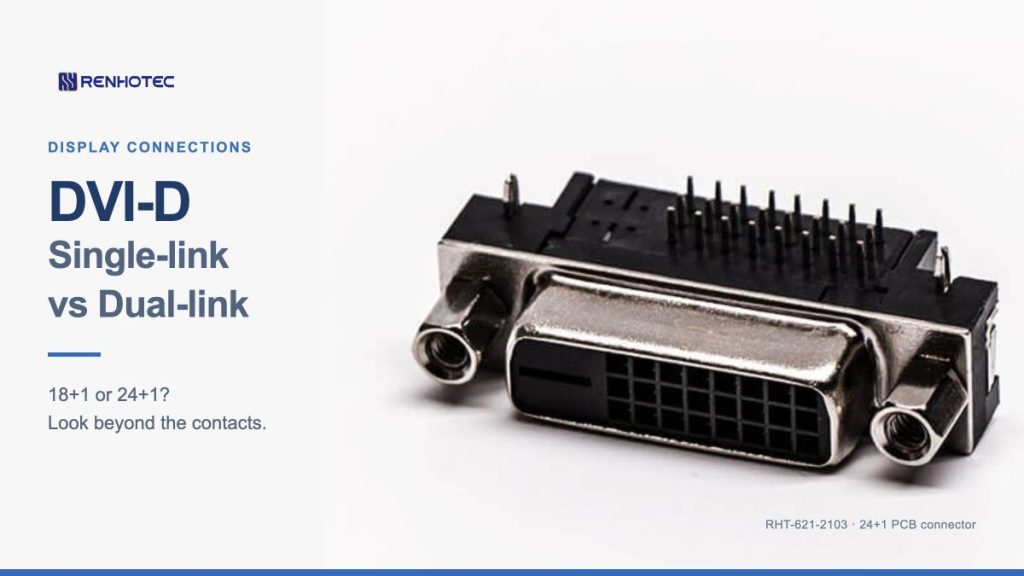
A DVI cable can fit the socket and still fail to deliver the display mode you need. The useful distinction is between the contact pattern you can see and the signal path the equipment actually provides.
DVI-D single-link is commonly identified as 18+1; dual-link as 24+1. The extra six positions provide additional digital data paths for one display; “dual-link” does not mean two monitor outputs. A fully populated socket, however, does not prove that its device drives both links. Start by identifying the connector, then check the source, cable, any adapter and the display input.
Read the contact pattern first
In the usual 18+1 and 24+1 notation, the first number counts the contacts in the rectangular array; the “+1” is the separate flat blade. These are also described as 19-pin and 25-pin DVI-D. For example, StarTech identifies its DVIDSMM1M single-link cable as 19-pin and its DVIDDMM1 dual-link cable as 25-pin.
Single-link pattern
18+1

Six positions are absent in the center of the array.
Dual-link pattern
24+1
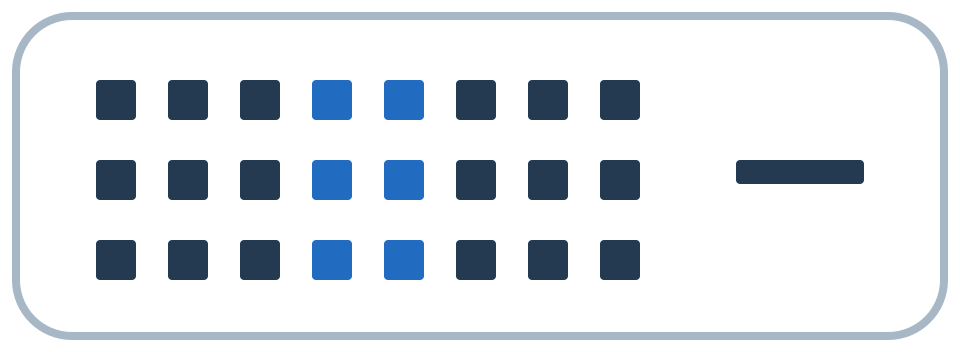
The six additional positions are highlighted in blue.
Check the plug and socket separately. A cable’s contact population is easier to see than the wiring behind an equipment socket. Do not count the metal shell or the fixing screws as contacts.
Also distinguish DVI-D from DVI-I. DVI-D carries digital video; DVI-I includes analog connections as well. The additional contacts around the blade on DVI-I are not the six central contacts that distinguish the two DVI-D patterns. A 24+5 connector therefore answers a different question from an 18+1 versus 24+1 comparison. StarTech’s DVI identification guidance lists these interface types separately. Never force a plug whose contact pattern does not match.
Check the whole path before choosing a cable
Write down the required resolution and refresh rate, together with the exact display input you intend to use. “DVI monitor” or “high resolution” is not a complete requirement. The display’s manual should identify the modes supported through that input; the source or dock documentation should identify what its output can deliver.
Check each part of the connection
- Source outputPC, graphics card or dock
Actual DVI link support - Adapter, if usedDirection, output link type
Supported display modes - DVI cableCorrect connector pattern
Specified link type - Display inputRequired resolution and Hz
Supported through DVI
A concrete example comes from Dell: its support guidance explains that E-Port docks use dual-link-style DVI connectors but are wired for single-link operation. Changing the cable cannot supply a second link that the dock does not output. Dell also calls out the need for a suitable display, video output, cable and any intervening adapter. See Dell’s video-display FAQ.
Can a dual-link cable serve a single-link connection? Yes, where its connector fits the equipment and the cable is specified for that use. For example, Eaton lists its P560-006 DVI-D cable for dual- or single-link equipment. It does not upgrade a single-link output. Conversely, an 18+1 cable does not supply the extra paths needed for a mode that requires dual-link operation.
Use resolution figures as specifications for a named product and operating mode, rather than assigning one universal ceiling to every connector. A cable or adapter advertised for one resolution does not establish support for a different refresh rate. If the exact mode is missing from the documentation, ask for confirmation before treating the connection as qualified.
“Active” does not mean “dual-link”
With DisplayPort-to-DVI adapters, three details are easily mixed up: the type of input signal, whether conversion is active, and whether the DVI output is single-link or dual-link. Read those fields separately.
| Adapter | Conversion and DVI output | What the specification establishes |
|---|---|---|
| DP2DVI2 | Passive; single-link | Requires a DP++ source. Listed up to 1920 × 1200. |
| DP2DVIS | Active; single-link | Lists a 25-pin DVI-D connector, but single-link AV output. Listed up to 1920 × 1200. |
| DP2DVID2 | Active; dual-link | Explicit dual-link conversion, listed up to 2560 × 1600 at 60 Hz. USB power is required. |
These are StarTech specification examples, not Renhotec products or a compatibility recommendation for an unnamed system.
The middle row is the useful counterexample: a 25-pin connector and active conversion still do not establish dual-link output. Check the output specification, not just a photograph or the word “active” on the listing.
DP++ means DisplayPort dual-mode support; it does not mean dual-link DVI. Eaton’s video-adapter guide explains the single-link DVI path through a passive DP++ adapter. It also cautions that most adapters work in one direction. Record “DisplayPort source → DVI display,” for example, instead of assuming the same device will work in reverse.
Work through three common connection changes
Choose the connection around the equipment you are keeping. These examples show which specification to check first; the listed display mode is a requirement to verify, not a promise for every product with that connector.
01 · Keep the existing DVI output
Replace a cable in a working system
Record the working resolution and refresh rate before removing the old cable. If both equipment manuals permit that mode through a single-link connection, a correctly specified single-link replacement is a candidate. A dual-link cable can also be suitable where it is specified for that use and its plug fits, but it will not improve an already correct image merely by adding contacts.
Match both ends, link type and required length. If you are changing the cable length or adding a coupler, treat that as a changed connection and verify it again. Do not assume the old cable’s successful short run proves a longer replacement.
02 · Keep a dual-link DVI display
Move to a DisplayPort computer
If the display manual requires dual-link DVI for the intended mode, look for an adapter that explicitly converts DisplayPort input to dual-link DVI output. A passive DP++ adapter or an active single-link adapter does not meet that requirement.
Check the exact mode, any monitor exclusions and the power connection. The DP2DVID2 example above lists 2560 × 1600 at 60 Hz and USB power. That makes its specification relevant to that requirement; it does not certify an unnamed monitor. The DVI cable after the adapter must also support the required link type.
03 · Keep a DVI display, change the source interface
Check HDMI or USB-C conversion separately
Do not choose an adapter by its DVI socket alone. StarTech’s HDDVIMF8IN HDMI-to-DVI adapter, for example, lists a 25-pin DVI-D connector and a maximum resolution of 1920 × 1200. Its complete specification, rather than the populated socket, determines whether it covers your intended mode.
With USB-C, first verify the source port’s video capability required by the chosen adapter. A USB-C connector is not enough to establish that video is available. Then check the adapter’s actual DVI output and the monitor’s accepted timing.
A PCB connector is only one component
When selecting a board-mounted DVI socket, keep its mechanical specification separate from the equipment’s video capability. A connector supplies the interface and terminations; the circuitry and routing behind it determine which signals are available.
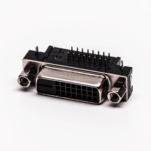
Right-angle · through-hole PCB mountView this exact connector →
The RHT-621-2103 product page confirms that contact arrangement, orientation, mounting method and nut construction. Those details make it a relevant 24+1 component example. They do not establish a finished system’s maximum resolution, refresh rate or compatibility with a particular display.
For a PCB replacement, compare the exact footprint, mounting points, board-to-mating-face position and enclosure opening. A matching front face does not prove that the solder tails or fixing features fit the old board. Use a dimensioned drawing for the selected part; do not borrow one from a visually similar DVI socket.
The Renhotec DVI connector range is the relevant place to compare component candidates. Keep the system’s single-link or dual-link requirement in the design specification while checking each candidate’s mechanical details.
Separate a missing mode from a failed connection
A black screen, a missing resolution and an unstable picture call for different first checks. None of these symptoms alone proves that you bought the wrong link type. Begin with the simplest documented connection, then change one part at a time.
| What you see | First useful check | What the result tells you |
|---|---|---|
| No picture at all | Select the intended display input. Verify adapter direction and required power, then try a mode the source and display both document. | A successful basic mode establishes a working connection at that mode. It does not establish dual-link operation. |
| Picture works; required mode is unavailable | Compare the exact resolution and Hz with the output, adapter and display specifications. Include any dock or KVM in the path. | A documented limit identifies a capability mismatch. More populated contacts do not remove it. |
| Flicker or intermittent loss | Try a known-working cable of the required type and test a supported lower resolution or refresh rate. Compare a direct path if available. | Improvement narrows the investigation to the changed path or operating mode; it does not, by itself, identify the failed component. |
| Direct connection works; dock or KVM path fails | Keep the source, display and target mode constant. Add the intermediate device and its required cable segments back one at a time. | The failure follows the added path. Check its output limits, cables, power and configuration before replacing the display. |
This isolation approach follows StarTech’s DVI troubleshooting guidance: compare components with a known-working setup and try a lower supported resolution or refresh rate. A lower-mode success is a diagnostic step, not acceptance of the original requirement.
Seeing the monitor’s name is not the same as proving the video link. EDID communicates the display’s supported modes to the source; it is a separate part of the connection check. If the hardware documentation permits the target mode but the computer does not offer it, investigate display detection and the intermediary’s EDID behavior. StarTech’s DVI EDID-emulator documentation describes retaining display settings for KVM and extension paths. Do not use an EDID change to promise a mode beyond the hardware’s documented capability.
For a replacement request, supply the source and display models, required mode, cable length and any adapter in between. For a bare PCB connector, add the existing part number, mating-face photos and board drawing. This gives the supplier enough information to distinguish a mechanical replacement from a change to the video connection itself.