
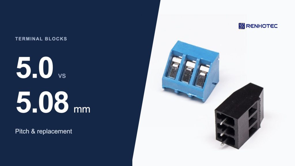
A 5.0 mm terminal block and a 5.08 mm terminal block have different nominal contact spacing. The difference is only 0.08 mm between adjacent positions, but it becomes 0.40 mm across a six-position row. Treat the two pitches separately when choosing a PCB footprint or a replacement plug.
Start with the exact part and its listed pitch, then verify the board footprint. For a pluggable connection, also confirm the mating pair. The right position count, a similar housing and a part that seems to fit are not enough to approve a replacement.
Two Renhotec products with different listed pitches
RHT-665-1535 is listed at 5.00 mm pitch, while RHT-665-1527 is listed at 5.08 mm. Both are listed as three-position, straight, through-hole products, so the position count and mounting description alone do not distinguish the pitch.
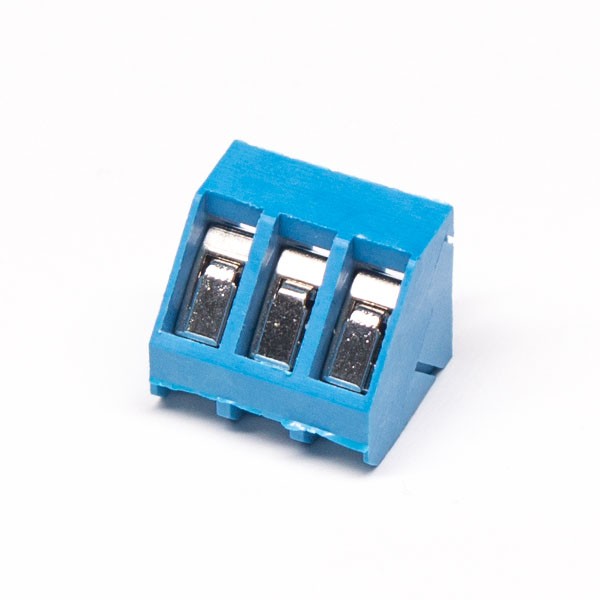
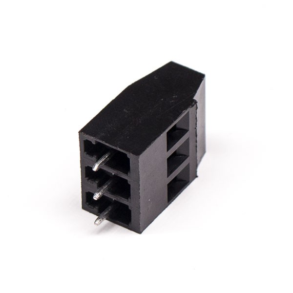
These are separate products, not two pitch options of a verified interchangeable series. The listed pitches support this comparison; the photographs do not show a measurable 0.08 mm difference. A dimensioned drawing is still needed to compare the complete footprint, pin dimensions and housing clearance.
For a uniform row of three positions, there are two intervals: 2 × 5.00 = 10.00 mm versus 2 × 5.08 = 10.16 mm. That is a calculated 0.16 mm difference between first and last centres, not a measured dimension from these photographs or a fit tolerance.
What 5.0 mm and 5.08 mm actually measure
Pitch is the centre-to-centre distance between adjacent positions in a regular row. A 5.08 mm pitch is exactly 0.200 inches; 5.0 mm is a different metric spacing. The Phoenix Contact PCB connector overview lists both spacings. A range heading such as “5.0/5.08” can group variants; resolve the full order code and drawing to one exact pitch.
Keep three dimensions separate: the spacing of adjacent centres, the span across a row of centres, and the overall housing width. Only the first is pitch. The second can be used to calculate pitch. The third includes the housing geometry.
The six-position Phoenix Contact 1150043 is specified at 5.08 mm pitch and 30.48 mm overall width. Its calculated first-to-last centre span is 5 × 5.08 = 25.40 mm. Dividing its width by six happens to give 5.08, but that coincidence is not a measurement rule for other housings.
Measure pitch without counting the wrong distance
Use the original part number and drawing first. If the part is unmarked, a longer row gives you more separation between the two nominal candidates. On a two-position part, there is just one interval and the difference remains only 0.08 mm.
- Isolate the equipment from power before handling the connection. Photograph the terminal, its markings and installed orientation before disturbing wiring. For a pluggable connection, record both halves.
- Identify one straight, uniformly spaced row. Choose the first and last contact centres you can locate reliably; count the positions between them, including both ends. Six positions give five intervals, not six.
- Measure that centre span along the row. Use the actual contact or pin geometry identified by the drawing. Do not substitute screw-head centres, wire-entry openings or plastic edges without confirming that they represent the same pitch.
- Calculate the average spacing:pitch = centre span ÷ (positions − 1)Record both the raw span and the interval count, so someone else can check the result.
When the centres are difficult to reach
For straight, equal-width pins, corresponding edges are separated by the same distance as their centres. For example, the left edge of the first pin to the left edge of the last pin gives the centre span. Measuring over the two outside edges includes one extra pin width. This is a geometric relationship, not a claim about the dimensions of a particular connector.
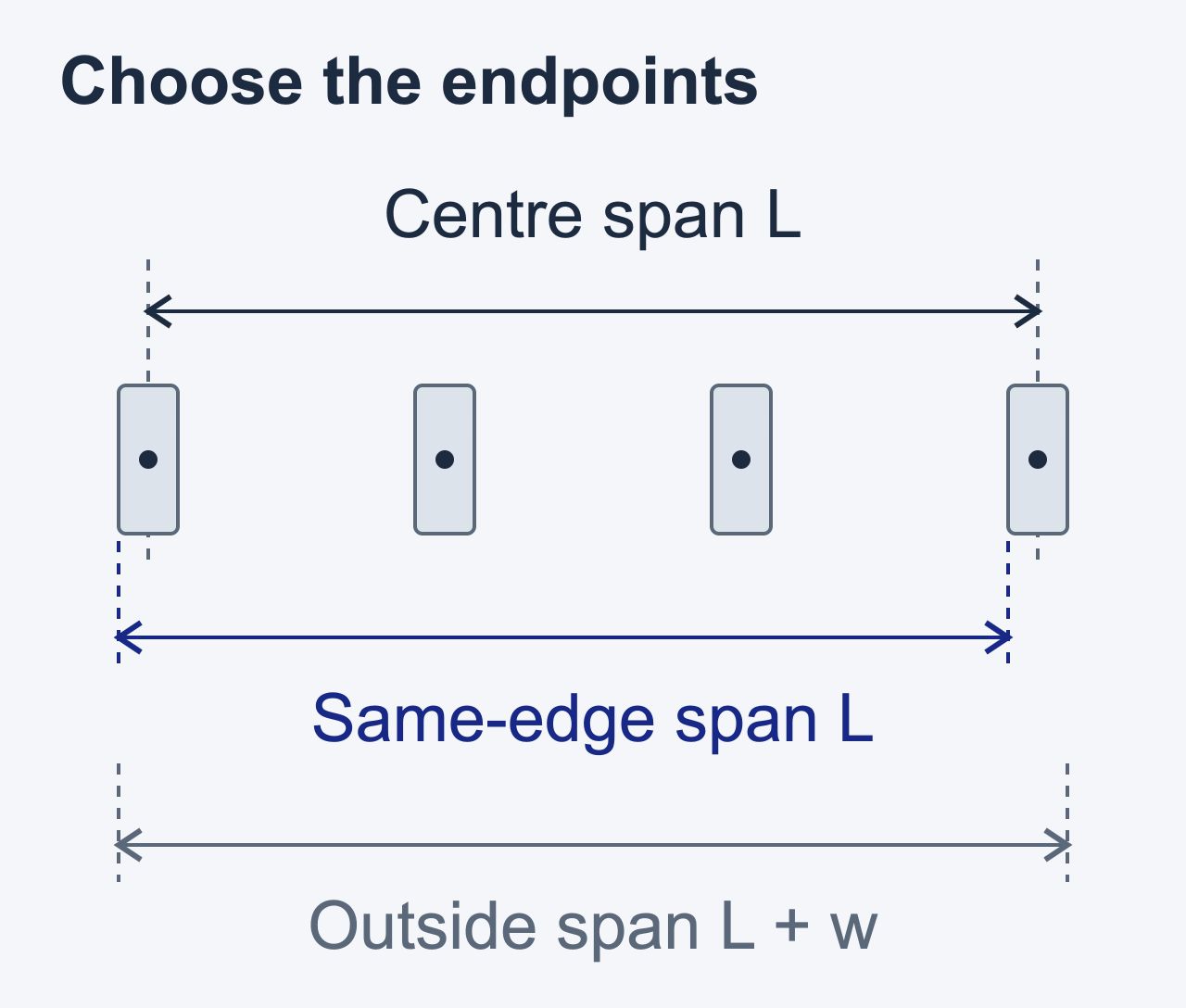
Use this relationship only when the edges are accessible, parallel and undamaged. Ordinary caliper jaws may not seat on the corresponding edges; do not force the jaws into a housing or estimate a hidden edge. If you cannot establish the endpoints reliably, obtain the drawing or use a suitable optical measurement method.
Clean the measuring faces, check zero and repeat the measurement with light, consistent force. A display resolution of 0.01 mm does not make every reading accurate to 0.01 mm. Mitutoyo distinguishes resolution from attainable accuracy; its caliper guidance also identifies jaw alignment, measuring force and temperature as error sources.
Read the result: nominal spacing is not a fit tolerance
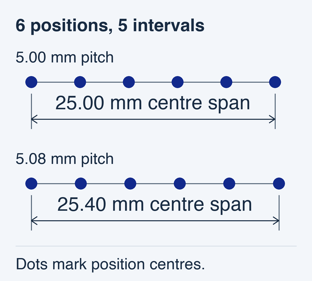
For a uniform row with N positions, centre span is (N − 1) × pitch. These calculated spans help distinguish candidates. They are not manufacturing tolerances or permission to move a pin by the amount in the last column.
| Positions | 5.00 mm pitch |
5.08 mm pitch |
Span difference |
|---|---|---|---|
| 2 | 5.00 | 5.08 | 0.08 |
| 3 | 10.00 | 10.16 | 0.16 |
| 6 | 25.00 | 25.40 | 0.40 |
| 12 | 55.00 | 55.88 | 0.88 |
A six-position span of 25.40 mm gives 25.40 ÷ 5 = 5.08 mm, so 5.08 mm is the nominal candidate to check against the drawing.
If a hypothetical reading is 25.20 mm, the result is 5.04 mm—halfway between the candidates. Do not round it to whichever part is available. Check the endpoints, alignment, part condition and measurement uncertainty; leave the pitch unconfirmed if the evidence cannot distinguish them.
A longer span makes the nominal difference larger, but does not remove bent-pin, endpoint or instrument errors. Nor does a plausible pitch result confirm mating compatibility. A short plug may appear to enter without establishing correct contact engagement. Do not force it, bend pins or enlarge PCB holes to compensate for an unidentified mismatch.
Choose the replacement path
First distinguish a fixed PCB terminal from a pluggable connection. In a fixed terminal, the wire terminates in the soldered component. A pluggable connection has a removable wire-side connector and a mating board-side connector. Establish which part must remain in the equipment before looking for alternatives.
Replace the wire plug
The installed header is the reference.
- Identify its manufacturer, series and full order code.
- Find the proposed plug in the manufacturer’s mating-part information.
- Compare coding, latch or flange, contact geometry and cable exit.
Replace the PCB terminal
Check the footprint and connection.
- For a fixed terminal, check wire termination; for a pluggable header, also verify the existing plug.
- Compare the footprint, pin cross-section, tail length and fixing features.
- Check body clearance, wire routing and removal access in the enclosure.
For a pluggable connector, check the named mating part
On the Phoenix Contact 1150043 page, “Compatible products → Mating parts” includes header 1755778, MSTBVA 2,5/6-G-5,08. That is a named pairing to investigate, rather than a match inferred from “six positions, 5.08 mm.” It does not establish interchangeability with a Renhotec part or another manufacturer’s connector.
Check the full order code, including any coding or fixing options, against the installed assembly. Then compare the drawings in the same viewing direction. A front view and a solder-side view can reverse the apparent arrangement; a photograph with the right number of contacts does not establish the circuit assignment.
If the original pair cannot be identified, replacing both halves may be an option, but it is an engineering change. The board holes, wiring, enclosure and application requirements all need review. Record which components may change before asking for alternatives.
Check the wire and ratings after the geometry
Once you have a plausible mechanical match, review the exact part’s connection and electrical data. Solid wire, stranded wire and wire fitted with a ferrule can have different allowed ranges. Include the conductor type and ferrule arrangement, not just a nominal wire size.
Use the specified strip length and, for screw terminals, tightening torque. Compare current, voltage, operating temperature and required approvals under the applicable conditions. The Phoenix Contact example publishes separate connection-data and approval fields; a single headline current or voltage is not a substitute for that review. Do not transfer its values to another product.
Use the Renhotec terminal block range to narrow the candidates by pitch and construction. The RHT-665-1535 and RHT-665-1527 examples show why the exact pitch must stay in the request even when position count and mounting descriptions agree. Request the dimensioned drawing for the selected part before treating it as a footprint replacement. For a removable plug, use the pluggable terminal block range and verify the named mating part as well.
Send a replacement request that can be checked
Keep the measured facts separate from the proposed replacement. A useful request lets the supplier trace the installed part, repeat your calculation and understand what must remain unchanged.
- Identify
- Full markings and order codes; equipment model; side and solder-side photographs where accessible. For a pluggable connection, include both halves and their mating faces.
- Measure
- Position count, measured span, chosen endpoints, interval count and instrument. Include the original drawing or board footprint when available.
- Constrain
- Which components may change; wire type and size; ferrule arrangement; electrical and temperature requirements; enclosure and service-access limits.
For example: “Replace the removable plug only; the PCB header must remain. Six positions, five measured intervals. Recorded centre span: 25.40 mm. Please confirm the full mating-part code against the attached header markings and drawing.” The span supports identification; the confirmed pair is what supports the replacement decision.