
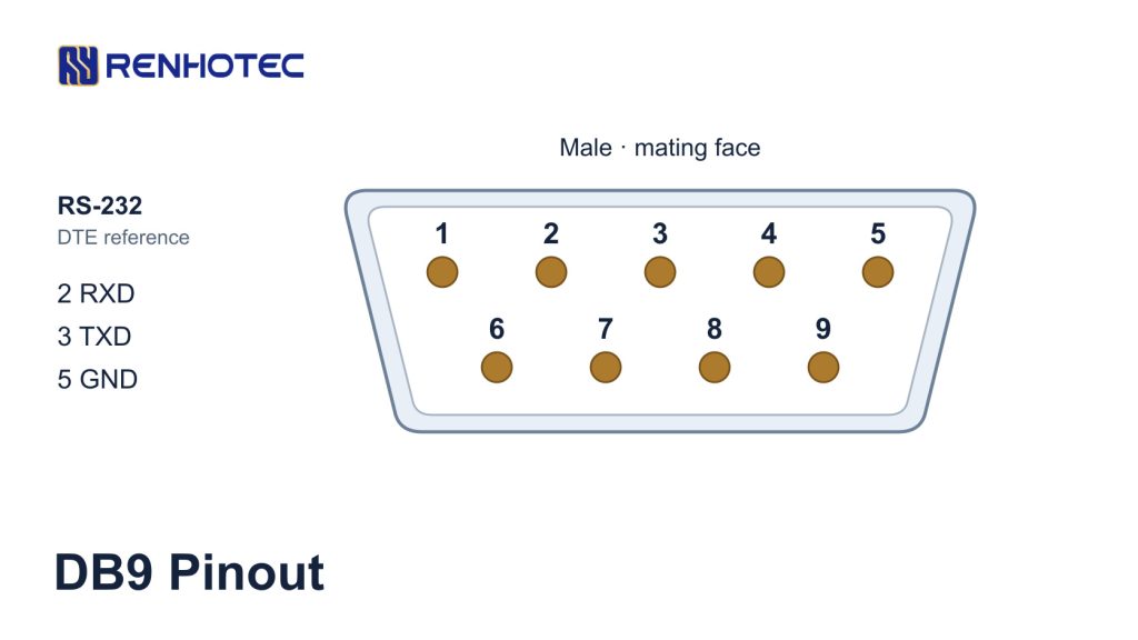
For a conventional PC-style RS-232 DB9 port, pin 2 receives data, pin 3 transmits data and pin 5 is signal ground. Those directions are relative to the DTE device, such as a PC. Before using that assignment, identify the connector’s viewing side and confirm that the equipment actually uses RS-232.
“DB9” is the familiar commercial name for the two-row, nine-contact D-sub connector. Its shell designation is DE-9: the E shell carries five contacts in one row and four in the other. The connector name identifies the physical interface; the equipment manual defines what each contact does. DigiKey’s D-sub shell reference explains the naming distinction.
DB9 male and female pin numbering
Both views below look directly at the mating face, the side that plugs into the other connector, with the five-contact row at the top. A male connector has exposed pins; a female connector has sockets. The two front views are mirror images, so contact 1 meets contact 1 when they mate.
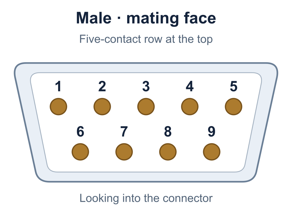
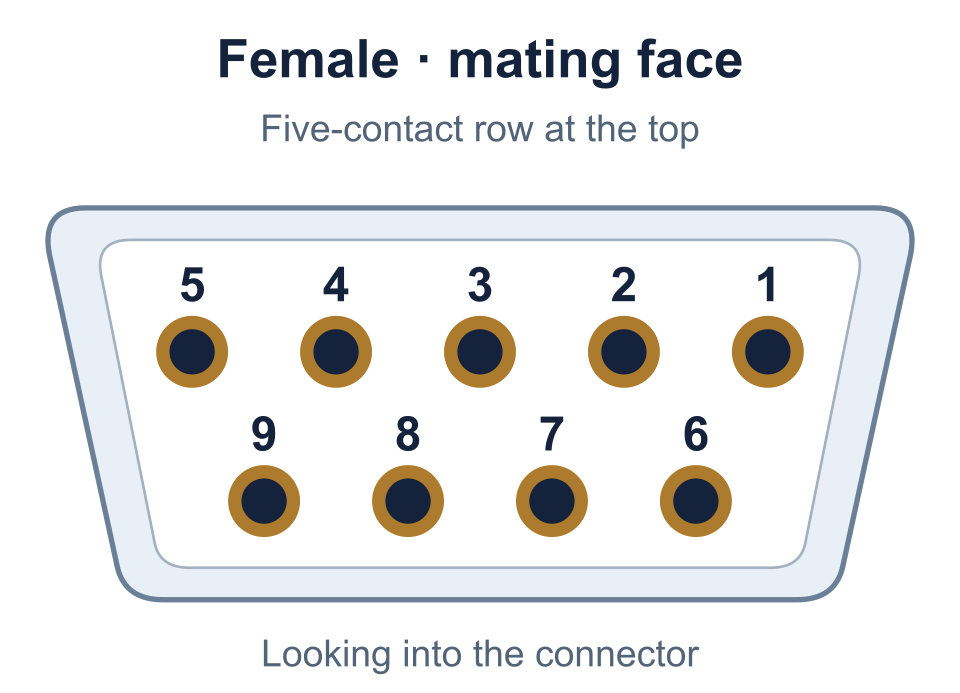
Looking at the solder side reverses left and right. Keeping the five-contact row at the top, a male connector’s rear view reads 5, 4, 3, 2, 1 across the upper row and 9, 8, 7, 6 below. A female connector’s rear view reads 1, 2, 3, 4, 5 above and 6, 7, 8, 9 below. The contact numbers themselves do not change. Use molded numbers or the connector drawing to confirm the terminals before soldering.
The male numbering is consistent with the NI 9870E pin-assignment drawing; the socket view can be checked against the female connector shown in TI’s TRS3122E evaluation-module guide. These illustrations show contact positions, not dimensions or a PCB footprint. A board drawing may show the component side or the underside, and a right-angle connector’s tails need their own footprint drawing.
RS-232 DB9 pinout: pins and signal direction
The signal map below uses the common PC-style nine-pin RS-232 assignment. Input and output mean into or out of the DTE. The five-contact row is at the top, as in the male mating-face view above.
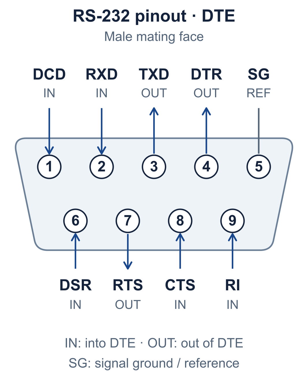
- Into the DTE: 1 DCD, 2 RXD, 6 DSR, 8 CTS and 9 RI.
- Out of the DTE: 3 TXD, 4 DTR and 7 RTS.
- Signal reference: 5 SG, also labeled GND or COM.
If the equipment uses a female DTE connector with this assignment, the mating-face positions are mirrored but the signal numbers stay the same. A DCE port has different input/output directions. Confirm the equipment’s role from its documentation, not its male or female contacts.
All nine pin assignments and signal functions
Directions are relative to the DTE. On smaller screens, scroll sideways for the function column.
| Pin | Signal | At the DTE | Function |
|---|---|---|---|
| 1 | DCD | Input | Data Carrier Detect: carrier or link status from the DCE. |
| 2 | RXD | Input | Received Data: serial data arriving at the DTE. |
| 3 | TXD | Output | Transmitted Data: serial data leaving the DTE. |
| 4 | DTR | Output | Data Terminal Ready: the terminal indicates readiness. |
| 5 | SG / GND / COM | Reference | Signal ground shared by the serial signals. |
| 6 | DSR | Input | Data Set Ready: the DCE indicates readiness. |
| 7 | RTS | Output | Request To Send: a control signal used in hardware flow control. |
| 8 | CTS | Input | Clear To Send: a control signal that can permit transmission. |
| 9 | RI | Input | Ring Indicator: modem ring status. |
A device may implement only some of these signals; an unused contact is not automatically available for another purpose. The assignments are documented in the NI 9870E manual, Table 2. Its receiver and transmitter specifications also distinguish input from output signals. Industrial equipment may omit modem-status functions or give them device-specific behavior, so check the device manual as well as the connector table.
Pin 5 is the signal reference, not a supply output. Pin 9 is RI in this assignment, not a universal 5 V or 12 V feed. If the device manual specifies a powered serial port, use that model’s documented assignment. The metal shell and cable shield also need their specified termination rather than an assumed connection to pin 5.
Why DTE and DCE matter more than connector gender
A PC serial port is the familiar example of data terminal equipment (DTE); a modem is the familiar example of data communications equipment (DCE). With the conventional assignment, a DTE sends on pin 3 and receives on pin 2. A DCE accepts that transmission on pin 3 and sends back on pin 2.
This explains a common documentation trap: a DCE drawing can call pin 2 “RXD” even though that device drives the contact. The signal name is referenced to the DTE. Read the manual’s direction column or transmitter/receiver description before deciding to cross the wires.
Traditional PC DTE ports are male and modem DCE ports are female, but connector gender alone cannot establish a device’s role. Industrial products and adapters can use different mechanical arrangements. Digi’s DTE/DCE guide describes the convention and why like-role connections need a crossover.
Straight-through or null modem: choose the wiring
Start with the role of each port. A conventional DTE-to-DCE connection keeps the data contacts on the same numbers. Two DTE ports need the transmitter at each end connected to the receiver at the other.
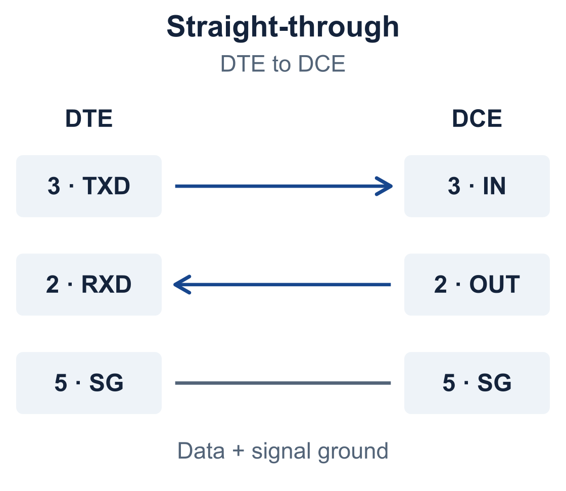
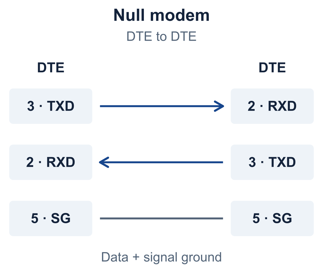
The diagrams show logical data paths, not contact positions. Add the control connections required by both devices. A fully wired straight-through nine-pin cable connects 1 → 1 through 9 → 9.
When a three-wire null modem is enough
The null-modem arrangement shown above becomes a three-wire cable when only pins 2, 3 and 5 are connected. Both DTE devices must support operation without hardware handshake lines.
Set flow control to none only if both devices permit it, or use supported software flow control on both ends. A program configured to wait for CTS may send nothing through a three-wire cable even when TXD and RXD are correctly connected. DCD or DSR requirements can also prevent communication.
When three wires are not enough
If both DTE devices require RTS/CTS handshaking, that pair normally crosses too: pin 7 at one end reaches pin 8 at the other, and pin 8 returns to pin 7. DTR, DSR and DCD connections depend on the equipment and software. A cable sold as “null modem” may include cross-connections, local loops or a different subset of contacts; obtain its wiring table instead of adding jumpers by guesswork.
The Digi AccelePort Xr guide, printed page 23, shows a nine-pin null-modem example with crossed data and control lines. Its three-wire discussion illustrates why hardware handshaking must be considered separately. Follow the wiring required by your actual pair of devices.
A DB9 male-to-female adapter addresses mating geometry. Check its internal connections to determine whether it preserves or changes the pin mapping. “Male-to-female” does not mean straight-through, and “straight” in a connector description can refer to body orientation rather than wiring. A passive adapter does not convert the serial protocol.
When this RS-232 pinout does not apply
A nine-pin D-sub can also carry RS-422, RS-485 or proprietary signals. A matching plug therefore does not establish electrical compatibility. Check the interface mode and the model-specific pinout before using an RS-232 cable.
For a concrete contrast, Moxa’s two-wire RS-485 guidance assigns DB9 pin 3 to B (+) and pin 4 to A (−). That is a differential pair, not RS-232 TXD and DTR. Moxa also notes that other manufacturers use different definitions. Compare signal polarity and the complete device diagrams; A/B letters alone are not enough to establish a match.
RS-232 is not a TTL UART connection
A microcontroller header labeled TX, RX and GND may use logic-level UART signals. It is not electrically interchangeable with an RS-232 port. TI’s TRS3122E guide shows a transceiver between the logic interface and the RS-232 connector. Crossing TX and RX with a passive cable does not provide that level conversion.
The same distinction applies when choosing a USB adapter: select a USB-to-RS-232 adapter for an RS-232 device, not a USB-to-TTL UART lead. For a multi-interface adapter, select the required RS-232 or RS-485 mode and use the pinout for that mode.
Check the cable before troubleshooting software
Separate a wiring fault from a serial-setting problem with a short, repeatable check:
- Identify both endpoints. Record the device model, port label, interface mode and DTE/DCE role. Keep the two port pinouts together; a connector photograph does not supply these details.
- Confirm the viewing direction. Locate pin 1 on each mating face. When working at solder cups or PCB tails, use the rear or footprint view specified by the connector drawing.
- Map the disconnected cable. Disconnect it from both devices and all power before using a continuity meter. Check which contact at end B connects to each required contact at end A, then check for unintended shorts between contacts. Record numbers rather than relying on wire colors.
- Match control requirements. Compare the measured map with the equipment’s required TXD, RXD, reference and handshake connections. Identify any deliberate loops or shield connections in the assembly specification.
- Check serial settings. Select the actual COM port and match baud rate, data bits, parity, stop bits and flow control to the device manual. A physically correct cable cannot correct a settings mismatch.
| Symptom | Useful next check |
|---|---|
| No communication in either direction | Confirm the COM port and interface mode, then compare straight-through versus crossover requirements and the measured cable map. |
| Only one direction works | Trace each TXD-to-RXD path separately. Check receive settings and whether flow control blocks the other transmitter. |
| Characters arrive but are unreadable | Compare baud rate, parity, data bits and stop bits first; if they match, investigate cable integrity and the installation environment. |
| Transmission stalls | Check whether the application expects CTS, DSR or DCD, and whether the selected cable carries the required control signals. |
These checks narrow the fault; a symptom alone does not prove its cause. An adapter loopback test, when supported by its manufacturer, tests only the path included in that loop. It does not establish compatibility with the remote device.
Choose the connector and specify the complete assembly
Once the pin map is settled, select the mechanical part for the installation. For a cable terminated by soldering, Renhotec RHT6811138 is a nine-pin male D-sub cable connector with stamped solder contacts. For a board-mounted interface, RHT6810402 is a straight, male through-hole PCB connector. Their mounting methods differ; neither product name establishes an RS-232 circuit or a completed cable’s wiring.
For a replacement or custom assembly, provide both device models and port drawings, the male/female contact type at each cable end, and an end-to-end pin table. Add the required length, cable exit direction, backshell clearance, locking hardware, shield termination and continuity-test requirements. Include any powered-port contacts explicitly rather than treating them as spare pins.
Use the Renhotec D-sub connector range to compare physical options. If the remaining question is pin count, housing layout or mounting style, the D-sub connector selection guide covers those choices. The device pinouts and assembly drawing should stay with the selection so that the connector, wiring and installation are specified together.