
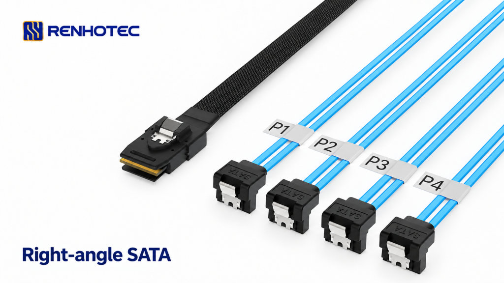
Renhotec RHT-726-2010 is worth shortlisting when four SATA drive connections need angled cable exits and the space beside those exits is clear. It combines one straight SFF-8087 Mini-SAS end with four right-angle SATA 7-pin ends. The angle is at the drives; it does not reduce the space needed behind the straight Mini-SAS plug.
For a controller-to-drive connection, the SFF-8087 port must support SATA drives and match the cable’s forward-breakout wiring. Each drive also needs a separate power connection. Once those conditions are established, compare the installed connector direction, the surrounding space and the route to all four bays.
Check the exit with the drive in its installed position
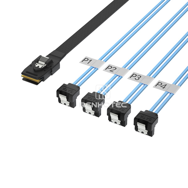
A right-angle plug changes where the cable leaves the connection. It can help when a panel blocks a straight exit but leaves a usable route alongside the socket. If that side is occupied by a wall, another drive or the power connector, the angled exit can create a new obstruction.
- Place the drive in its intended tray or bracket orientation. Identify the SATA data socket and the adjacent power socket.
- Compare the keyed SATA opening and latch position with the cable drawing. Use these fixed features to establish the exit direction; rotating a product photograph does not change which way the plug will fit.
- Check the route with the power plug included. Leave access to press the data-plug latch and withdraw the connector along its mating direction, following the equipment’s service procedure.
Use an annotated rear or side view of the installed drive when specifying the angle. Mark the socket, the nearby obstruction and the desired cable path. Terms such as “up,” “down,” “left” and “right” need that viewing reference. For example, StarTech’s angled SATA range distinguishes opposite exit directions; its naming and dimensions do not identify the orientation of this Renhotec assembly.
If the required exit points into an obstruction, compare another SATA-end orientation in the Mini-SAS cable range. If the obstruction is behind the SFF-8087 host port, changing only the SATA ends will not solve it.
Read the dimensions as connector views, not installed clearance
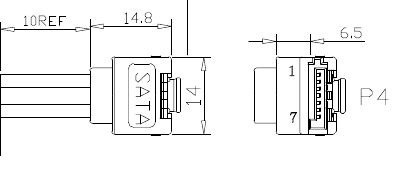
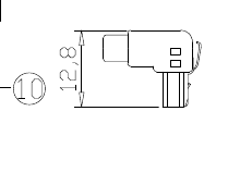
The RHT-726-2010 R1.0 drawing, dated 17 June 2024 provides several views of the SATA end. Keep each callout with its view when comparing it with a tray or enclosure drawing.
| Drawing callout | How to use it | What still needs checking |
|---|---|---|
| 14.8, 14 and 6.5 mm | Compare the indicated SATA-end views with the same axes in the mating assembly. | The seated position, neighboring power plug and access to the latch. |
| 12.8 mm | Read the side-profile dimension between its shown extension lines. | The projection beyond the installed drive and the space needed to connect or remove it. |
| 500 ±20 mm | Use the overall assembly length between the drawing’s indicated datums. | The routed distance to every drive, including turns and connector positions. |
| 290 REF | Locate the reference span marked along the sleeved portion. | Usable branch reach after the breakout; do not calculate it simply as 500 minus 290. |
A 12.8 mm profile callout is not a promise that the assembly fits a 12.8 mm gap behind a drive. The drawing does not include the mating depth, your power plug or the space needed to operate the latch. Check those together in the installed assembly. Request the applicable cable bend limit before fixing the route around a tight corner.
Check all four routes before choosing the assembly
Start with the furthest drive, then check the nearest one. The furthest branch must reach without pulling on either connector; excess cable at the nearest bay must have somewhere to sit without pressing against a fan, cover or adjacent plug. Repeat the exit-direction check at each bay if drives face different ways.
RHT-726-2010 is a useful candidate when its SATA exits face open routing space, both data and power connectors can be seated and released, and the straight host end has sufficient room. A tray that requires a different exit direction or a tightly prescribed connector envelope needs another configuration or a drawing-based fit review.
For a RHT-726-2010 configuration request, send the controller and SATA drive models, the host port reference, and an installed-drive view showing the desired exit. Add the tray drawing, power-plug location and the required route to each of the four drives. Specify the supply length and orientation against the order drawing; the public sheet describes one 500 mm configuration.
The forward-breakout interpretation follows the cable’s R1.0 connections, the SFF-8087 controller assignments in SNIA SFF-9402 Rev 1.1, Table 8-1, and the SATA device signal roles in Viking Technology’s SATA SSD manual, Table 4-1. These references establish the connection roles; they do not qualify a particular controller, chassis or transfer rate.