
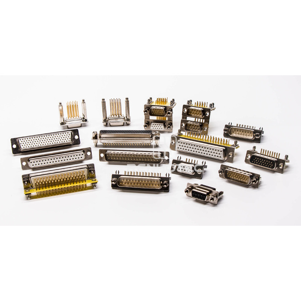
D-subminiature connectors are used for equipment I/O in control, instrumentation and communications. Their D-shaped metal shell provides a recognisable mating outline and helps prevent reversed insertion. Versions are available for board, panel and cable connections.
Shell and contact arrangement
Common standard-density contact counts include 9, 15, 25, 37 and 50. High-density arrangements include 15, 26, 44, 62 and 78 contacts. Contact count and shell size are different specifications: two connectors described as 15-position may have different row arrangements and mating dimensions.
Mixed-contact versions can combine signal, power or coaxial contacts. Check the complete contact layout, contact gender and mating drawing rather than selecting by the D-shaped outline alone.
Mounting and termination
For vertical and right-angle board connectors, compare the specified PCB footprint and enclosure clearance for each part. Cable connectors may use solder or crimp termination, depending on the design. Confirm the termination method, panel mounting, locking hardware and cable exit space for the selected part.
Mating and shielding
A similar shell does not guarantee interchangeability. Check the shell dimensions, contact pattern, hardware and applicable part specifications for both halves. Where shielding is required, the connector shell, cable screen and equipment grounding arrangement must work together.
For a replacement or new design, provide the mating drawing, required contact arrangement and installation dimensions. These details help narrow the options before electrical and environmental ratings are compared.