
For a straight-through Ethernet cable, use T568A at both ends or T568B at both ends. The two schemes swap the orange and green pairs; choosing B instead of A does not make a cable faster. Before checking the colors, identify pin 1 from the correct connector view.
The eight cable contacts are only part of an equipment connection. A replacement plug must suit the cable, while a PCB jack must also match the board footprint and electrical circuit.
RJ45 pinout: identify the view before the colors
The diagrams show the contact side of a plug: the gold contacts face you, the plug tip points away from you, the cable comes toward you and the latch is underneath. In this view, pins run from 1 on the left to 8 on the right. This is a view down onto the contacts, not into the cable entry.
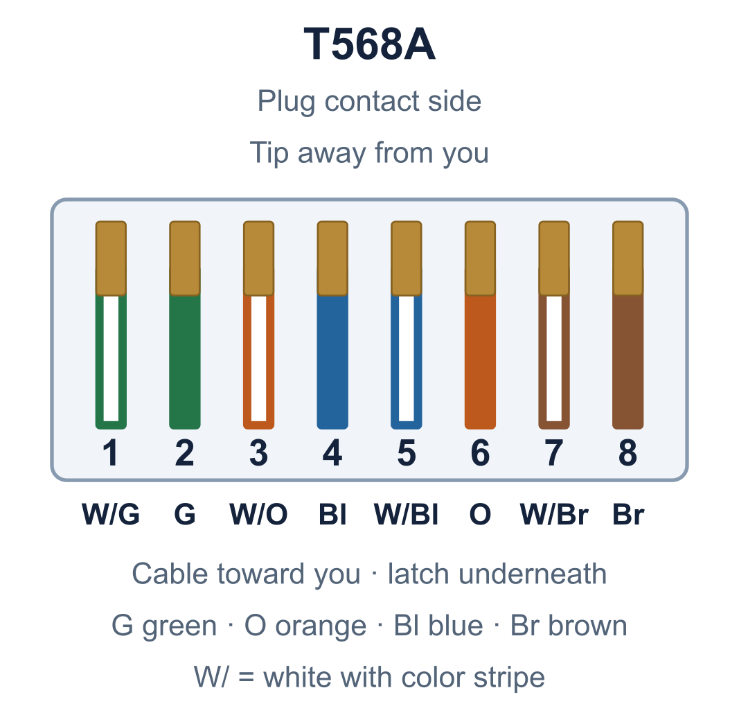
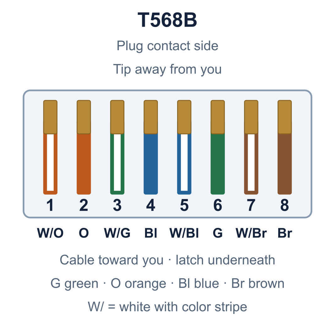
Eight-pin color reference in text
| Pin | T568A | T568B |
|---|---|---|
| 1 | White/green | White/orange |
| 2 | Green | Orange |
| 3 | White/orange | White/green |
| 4 | Blue | Blue |
| 5 | White/blue | White/blue |
| 6 | Orange | Green |
| 7 | White/brown | White/brown |
| 8 | Brown | Brown |
W/ in the diagrams means a white conductor with the named color stripe. The numbering and plug orientation can be checked in Siemon’s plug identification diagram, page 4.
A jack’s rear termination layout is not the same drawing. Punch-down terminals may be arranged in separate banks, and PCB solder tails can follow a different order. Use the jack’s A/B color legend for an insulation-displacement contact (IDC) termination, or its numbered circuit and footprint drawings for a PCB. Do not copy the left-to-right plug order onto an unmarked row of board pins.
T568A or T568B: which should you use?
Follow the project specification and the documented scheme used by the existing installation. Both schemes preserve the same four contact pairs. A change from A to B swaps the orange and green pairs between 1/2 and 3/6; blue remains on 4/5 and brown on 7/8. Fluke Networks compares the two assignments and their equal transmission performance.
| End A / end B | Result | When it fits |
|---|---|---|
| T568A / T568A | Straight-through: 1 → 1 through 8 → 8. | An installation specified for T568A. |
| T568B / T568B | Straight-through: 1 → 1 through 8 → 8. | An installation specified for T568B. |
| T568A / T568B | 1 → 3, 2 → 6, 3 → 1, 6 → 2; pins 4, 5, 7 and 8 remain straight. | The familiar two-pair crossover arrangement used for certain 10/100 Ethernet connections. Check the equipment requirement. |
A completed A/A patch cord and a completed B/B patch cord both have a straight-through pin map. That differs from terminating opposite ends of one cable A/B. When replacing a plug on an existing cable, identify the other end’s scheme before crimping the new one.
Auto-MDIX can let compatible Ethernet ports adapt to straight-through or crossover connections. Cisco’s Auto-MDIX guide describes that behavior and its configuration conditions for the covered switches. Verify support and settings on your equipment. Auto-MDIX does not repair broken conductors or split pairs, and the A/B example above is not a universal crossover recipe for every Ethernet mode.
Keep the pairs intact, especially pins 3 and 6
The four contact pairs are 1/2, 3/6, 4/5 and 7/8. Pins 3 and 6 are separated by the blue pair at pins 4 and 5. Arranging every pair as two adjacent pins would break that assignment.
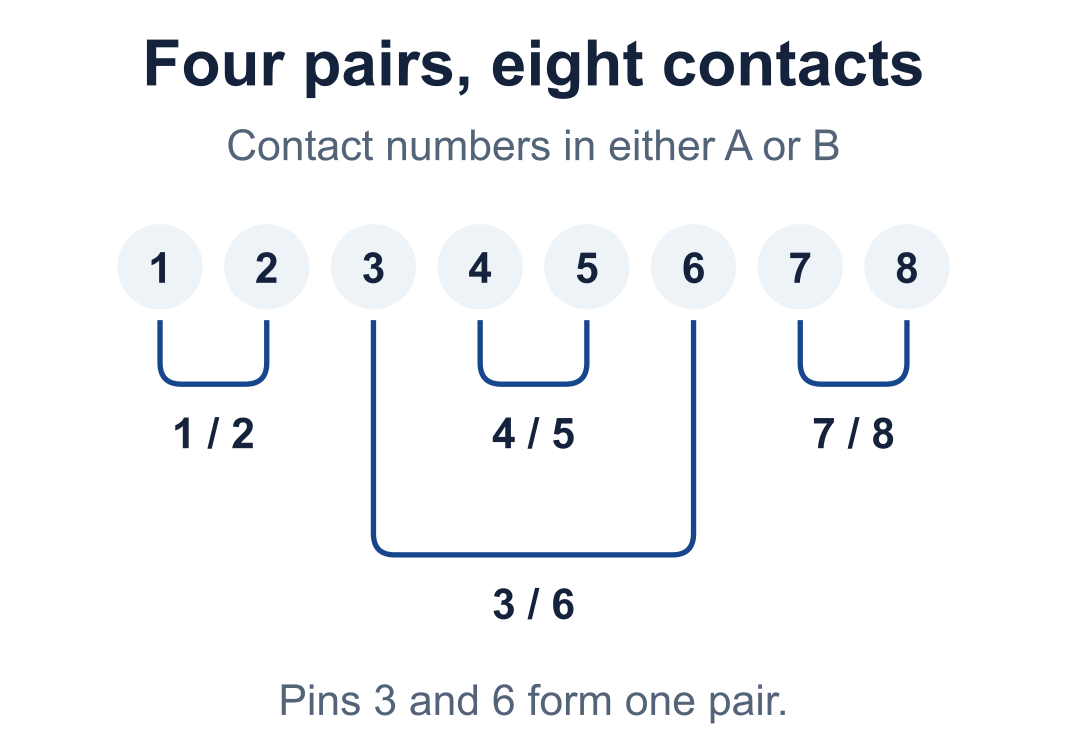
A split pair occurs when the conductors assigned to a signal pair come from different physical twisted pairs. If the same mistake is repeated at both ends, a simple continuity tester can still report 1 → 1 through 8 → 8. The cable can nevertheless suffer excessive crosstalk. Fluke Networks’ split-pair example shows why continuity and correct pairing need separate checks.
Preserve each pair’s twist close to its termination and follow the connector’s assembly instructions for stripping, untwist and strain relief. A single preparation length does not suit every crimp plug, field-termination plug or IDC jack.
For data, 10BASE-T and 100BASE-TX use two pairs; 1000BASE-T uses all four pairs, with transmission and reception on the same pairs. TI describes the four-pair operation in its Gigabit Ethernet reference design, section 2.2.2.1. A link that works at 100 Mb/s therefore does not establish that all eight conductors support a Gigabit connection. Do not treat the other pairs as spare power terminals.
RJ45, 8P8C and RJ11: what the names tell you
In Ethernet product listings, “RJ45” commonly means the eight-position, eight-contact modular interface, or 8P8C. P counts the available contact positions; C counts the contacts fitted. The Registered Jack naming system also includes wiring arrangements, so an RJ number is not simply a pin count. Same Sky’s RJ45 overview explains the commercial naming and connector structure.
Telephone connectors sold as RJ11 commonly use a narrower six-position body with fewer contacts fitted. Six positions do not automatically mean six connected wires or the same telephone circuit. Record the full P/C configuration and equipment pinout when comparing modular parts; a smaller plug fitting into a larger opening does not establish compatibility.
The RJ45 shape is also used for some console, serial and proprietary equipment ports. Read the port label and manual before connecting a network switch or PoE source. The T568A/B color chart describes conventional balanced Ethernet cabling, not a universal pin assignment for every eight-position port.
Choose the plug or jack for its installation
A cable plug, a punch-down jack and a PCB-mounted jack solve different termination tasks. For a replacement plug, match the specified cable category, conductor gauge, solid or stranded construction, insulated-conductor diameter, overall jacket diameter and shielding. The plug’s contact design and assembly tool must support that cable.
| Selection | What to compare | What can go wrong |
|---|---|---|
| Cable plug or field-termination plug | Cable construction, contact system, wire guides, strain relief and approved tooling. | Conductors fit the holes but the contacts or cable clamp do not suit them. |
| IDC or panel jack | A/B termination legend, cable range, panel retention and shield termination. | The visible terminal sequence is mistaken for the plug’s pin sequence. |
| PCB jack | Through-hole or surface-mount (SMT) footprint, locating pegs, shell tabs, height and entry direction. | The mating plug fits, but the connector cannot sit or solder correctly on the board. |
| Multiport jack | Port matrix, pitch, latch direction and access to plugs in every row. | The enclosure opening fits the body but blocks release tabs or adjacent cable boots. |
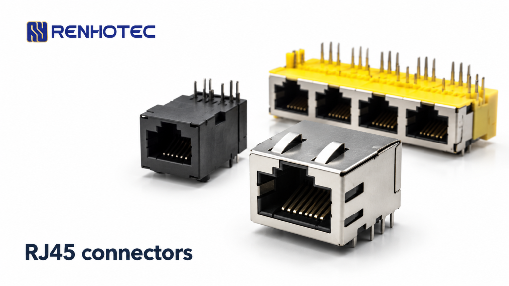
For a board-edge connection, Renhotec RHT-620-1201 is a shielded 8P8C socket with right-angle DIP through-hole mounting and no LEDs. Compare its drawing with the board and panel before considering it as a replacement.
For a denser panel, RHT-620-0723 has 12 ports in a 2 × 6 shielded arrangement without LEDs. Port count changes the mechanical layout; it does not by itself establish data rate, magnetics or PoE capability. The Renhotec modular connector range provides other layouts to compare.
Check magnetics, LEDs, shielding and PoE separately
For a conventional transformer-coupled copper Ethernet port, the Ethernet PHY (physical-layer transceiver), magnetics and connector form a signal path. The isolation transformers and related magnetic components may be separate board parts or integrated into the jack. Moving them into the jack changes the required circuit and footprint; it does not make every magnetic jack interchangeable.
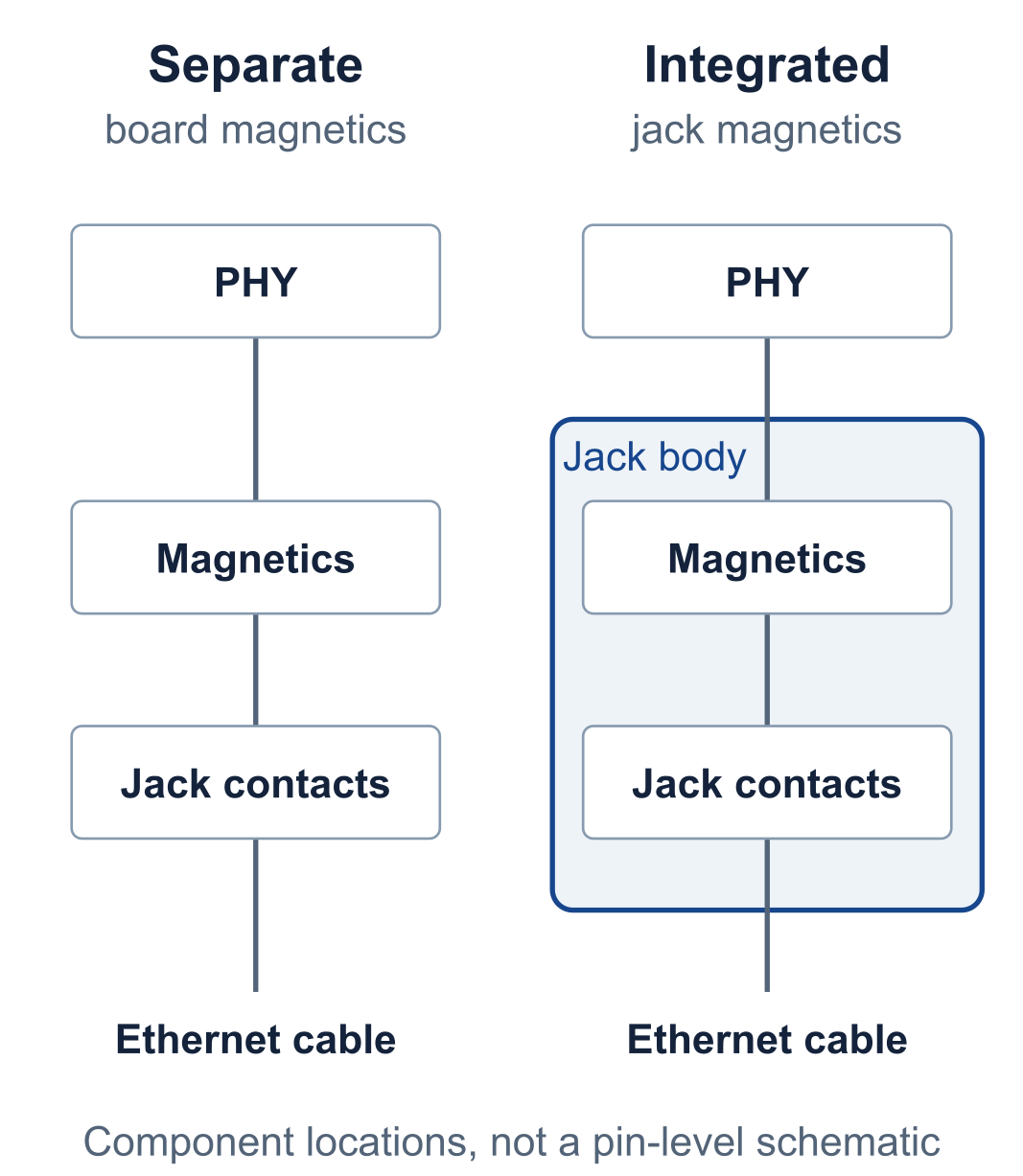
Compare the jack’s internal schematic with the PHY reference design, including pair connections, center taps, termination and any PoE connections. TI’s reference design shows the transformer connection between the PHY and RJ45. A front view cannot reveal this circuit.
- LEDs: check their pin assignments, polarity and drive requirements. Color alone does not define a universal speed or link indication.
- Shielding: plan the connector shell, cable shield and equipment chassis connection together. A metal shell does not establish an environmental seal or the performance of the complete installed link.
- PoE: confirm the required power standard and supported power level for the source, powered device, cable and connector. A passive power injector or proprietary powered port must not be assumed compatible with an IEEE PoE device.
Keep cable category and Ethernet speed as separate specification fields. Changing the color order does not upgrade the cable, and the connector’s shape does not qualify the complete channel for a data rate.
Terminate, test and diagnose the complete link
- Identify the connection. Confirm both port functions, the required speed and any PoE requirements. Disconnect the cable from equipment and power before reterminating it or making continuity measurements.
- Follow the selected termination system. Check the plug or jack instructions, choose the required A/B scheme, preserve the pairs, and secure the cable jacket in the strain relief.
- Check the wire map. Look for opens, shorts, reversals, crossed pairs and split pairs. Use a tester capable of detecting the faults you need to rule out; eight continuity lights do not certify a cable category.
- Verify operation. Check negotiated speed and the equipment configuration. Where required, qualify or certify the installed cabling against the project requirements, then test PoE delivery with suitable equipment.
| Symptom | Useful next check |
|---|---|
| No link | Confirm the port is Ethernet and enabled, check the cable wire map, and verify crossover requirements if Auto-MDIX is unavailable. |
| 100 Mb/s instead of 1 Gb/s | Confirm both ports support Gigabit and their settings permit it; test all four pairs, terminations and cabling performance. |
| Continuity passes, but the link is unreliable | Check for split pairs, excessive untwist, damaged cable, unsuitable terminations and interference in the installation. |
| Data works, but a PoE device does not power up | Check source and device compatibility, available port power, cable condition and the required PoE delivery under load. |
A wire map, a successful data link and a PoE load test answer different questions. Fluke Networks’ cable-and-network testing documentation separates wiring faults, bandwidth qualification and PoE testing. Use the relevant result when accepting an installation; a symptom alone does not prove its cause.
For an RJ45 connector inquiry, provide the mating interface and board drawing alongside the required cable, Ethernet mode and PoE specification. Include the panel opening, latch access and cable exit space so the mechanical selection can be checked with the electrical requirements.